Download 3 Phase Motor Starter Wiring Diagram Pdf free
The wiring diagram for the starter typically includes information such as the battery, ignition switch, solenoid, and starter motor. Each component has a specific role in the starting process, and the diagram helps you understand how they interact and work together. By referring to the diagram, you can diagnose any issues related to faulty.

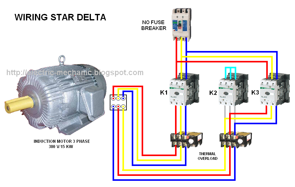
Star Delta Starter Connection Diagram and Wiring ETechnoG
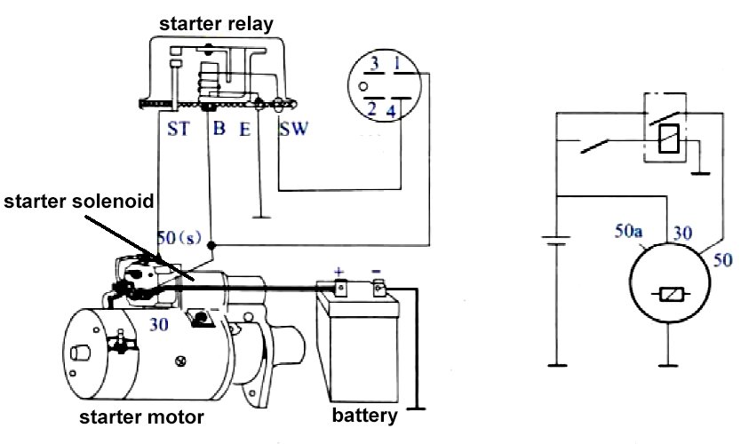
Terminal Starter Solenoid Wiring Diagram. In automotive electrical systems, the starter solenoid is a key component that helps to start the engine. It is responsible for engaging the starter motor and initiating the engine's rotation. The terminal starter solenoid wiring diagram illustrates the connection of the various terminals on the solenoid.
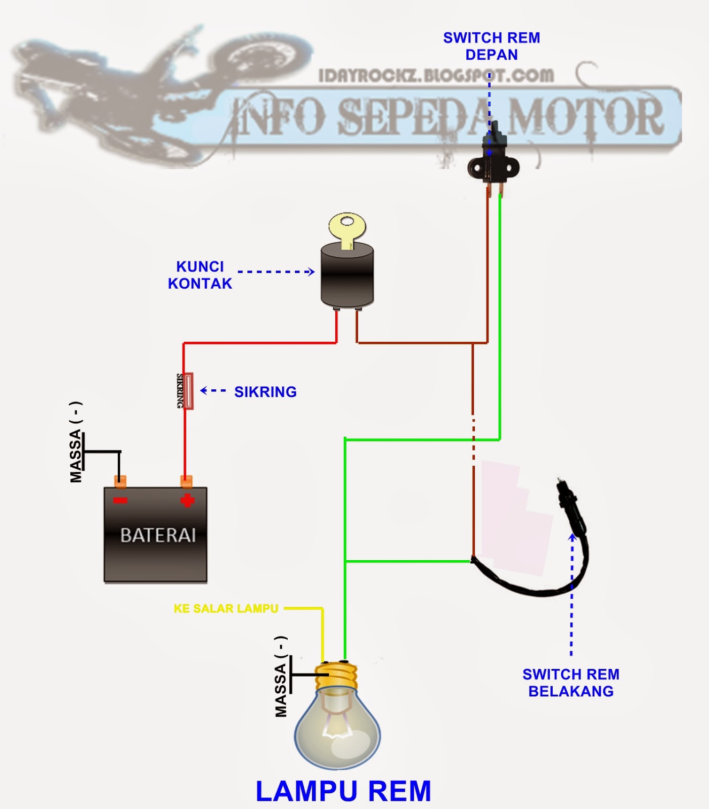
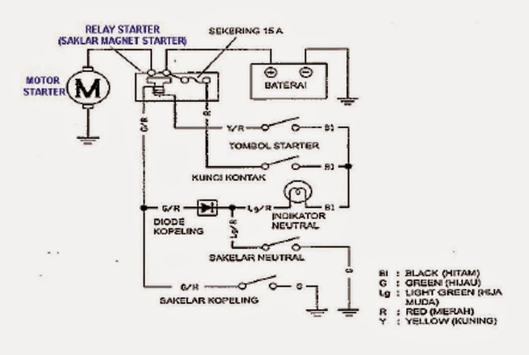
Wiring Diagram Sistem Starter Jupiter Z
The starter circuit. All the components are earthed to the metal car body. Only one wire is needed to carry current to each component. The starter switch is usually worked by the ignition key. Turn the key beyond the 'ignition on' position to feed current to the solenoid. The ignition switch has a return spring , so that as soon as you release.
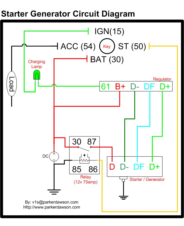
Delco Starter Generator Wiring Diagram Bestn
Components of starting system. 1. Battery. The automotive battery, also known as a lead-acid storage battery, is an electrochemical device that produces voltage and delivers current. In an automotive battery we can reverse the electrochemical action, thereby recharging the battery, which will then give us many years of service.
[DIAGRAM] Wiring Starter Diagram
The wiring diagram for a starter motor relay typically includes information about the power source, the control source, and the load. The power source is the battery, which provides the electrical energy needed to activate the relay. The control source is usually a switch, which is used to turn the relay on or off.

Ford 302 Starter Wiring Diagram troutfishingcr
Two cables usually connect the battery to the starter: a red wire and a black or greenish-yellow one. The red wire connects the battery's positive terminal to the solenoid, while the other cable connects the battery's negative terminal to the motor. The colors vary depending on the vehicle's year, make, and model.

3 Pole Starter Solenoid Wiring Diagram Wiring Diagram
Make sure that power is reaching the switch and that the switch itself is not faulty. Once the motor is running, press the stop button to stop the motor. The motor should come to a halt immediately. If the motor does not stop, check the wiring connections again and confirm that the stop button is functioning correctly.

Wiring Diagram For Starter Ford F 150 main kuiytgdb Electrical wiring diagram, Car starter, Ford
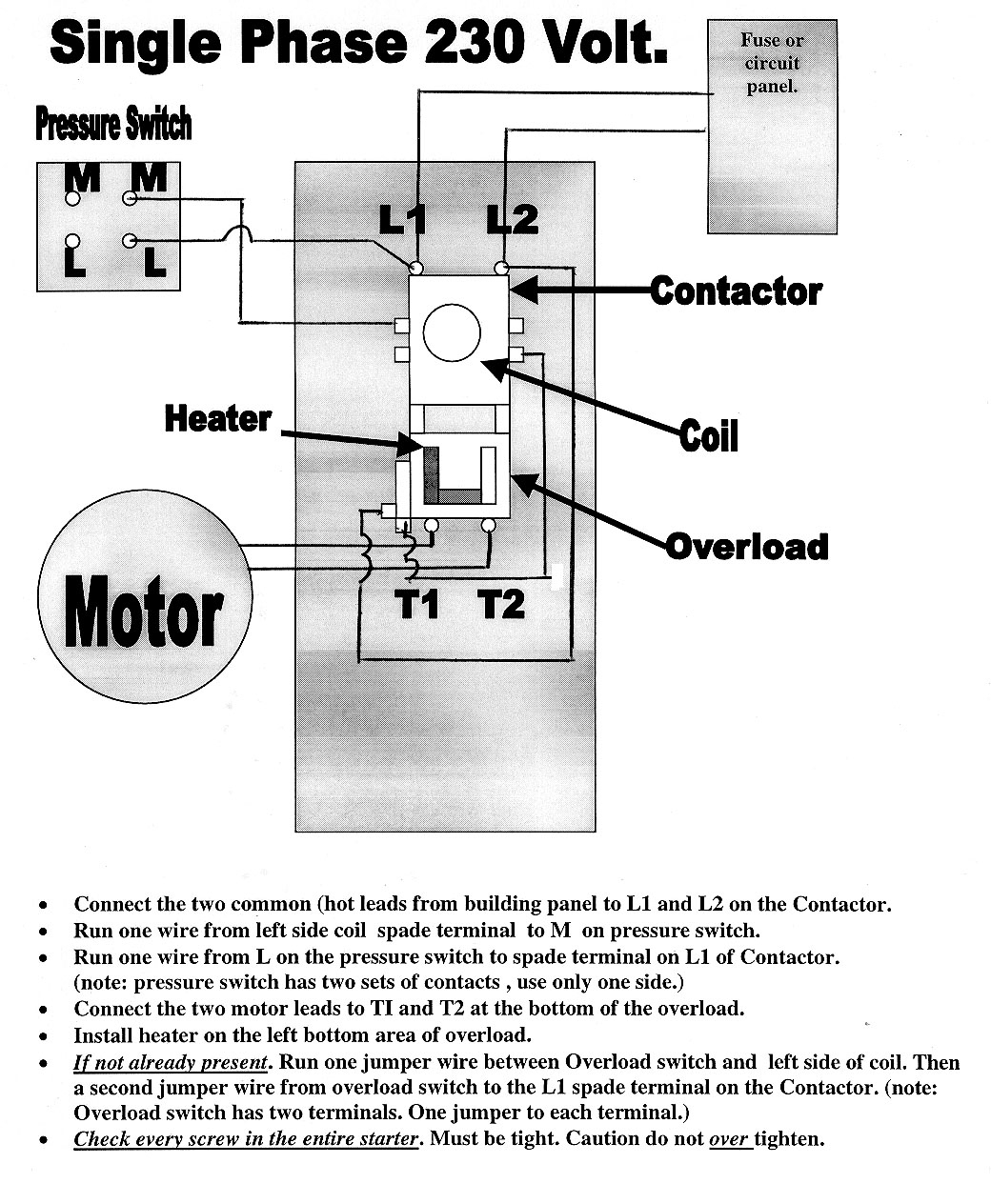
Power circuit wiring. The power circuit of the starter consists of the following components: MCCB (Q1) : Protects the circuit from short circuits.; Contractors: Main (1KM1), star (1KM2) and delta (1KM3).For switching. Overload relay. (OLR1) For protection against overloads.

Diesel Engine Starter Wiring Diagram Headcontrolsystem
The Starter Motor Wiring Diagram. Remember, the starting motor uses two wiring circuits to complete its operation. The first one is the control circuit, and the second one is a heavy electric circuit. The control circuit turns ON and OFF the solenoid and is controlled by the ignition switch. It consumes less current, and these cables are thin.
Wiring Starter Motor Diagram Collection
The auto start wiring diagram includes information on the power source, ignition switch, starter motor, solenoid, and various sensors and switches. It also shows the connections between these components and any relays or fuses that may be involved. This diagram is essential for understanding the functional operation of the auto start system and.

schematics and diagrams Saturn SL2 Starter Wiring Diagram?
Starter Solenoid Wiring Diagram. ples of electromagnetism in its work. When the ignition key is turned on, it sends an electrical signal to the solenoid, which then engages the starter motor and cranks the engine. It act as safety solenoid switch, preventing the starter motor from engaging unless the transmission is in neutral or park. It act.

DOL Starter Wiring Diagram (Direct Online Starter)
Wiring diagram sistem starter konvensionalsistem starter termasuk kedalam sistem kelistrikan engine/mesin.Bagi yang ingin melihat/mendownload gambar wiring d.
Square D Nema 1 Starter Wiring Diagram Square D Motor Starter Wiring Diagram Cadician's Blog
Standard duty "START-STOP" stations are provided with the connections "A". shown in the adjacent diagram. This. connection must be removed from all but one of the "START-STOP" stations used. Heavy duty and oiltight push button stations can also be used but they do not. have the wiring connection "A", so it must.

Powermaster Starter Wiring Diagram
The wiring diagram for a DOL stater is shown below. A direct online starter consists of two buttons, a GREEN button for starting and a RED for stopping purpose of the motor. The DOL starter comprises an MCCB or circuit breaker, contactor and an overload relay for protection. These two buttons, i.e. Green and Red or start and stop buttons.

[DIAGRAM] Wiring Diagram Sistem Starter Motor
A typical starter solenoid has one small connector for the starter control wire (the white connector in the photo) and two large terminals: one for the positive battery cable and the other for the thick wire that powers the starter motor itself (see the diagram below). The starter solenoid works as a powerful electric relay. When activated.
[DIAGRAM] Motor Starter Wiring Diagrams
sistem starter tipe reduksi adalah sistem starter yang memiliki gigi tambahan sebagai pereduksi putaran. Putaran starter direduksi dengan tujuan menghasilkan momen puntir yang kuat. Sehingga cocok untuk mesin-mesi yang memiliki kompresi tinggi seperti mesin diesel. Sistem ini juga didesain lebih kecil dari tipe konvensional.