Baru 29 Skema Pcb Filter Subwoofer Paling Modern Dan Nyaman, Skema Pcb
Subwoofer active low pass filter. Figura 1: The subwoofer active low pass filter board. This article presents a simple second order active low pass filter with an adjustable cutoff frequency between 20 Hz and 200 Hz. The circuit, which uses a single power supply, works on low power audio signal (that is, line audio levels) and is intended as a.
Skema Filter Subwoofer Frekuensi Transistor Polytron ⋆
BUY IC NE5532 ALLCHIPS. To facilitate the making of this filter subwoofer circuit I also share PCB Layout design below, with the size of PCB 107mm x 69mm. DIY Subwoofer Filter Circuit. This Subwoofer Filter NE5532 is tested with Power Amplifier SOCL 504, see this video: This most important circuit that using for subwoofer filter for you.
Skema Tone Control Plus Subwoofer
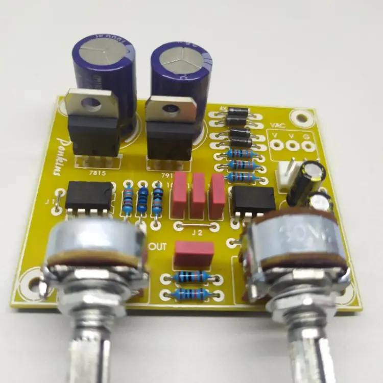
SWM222 adalah filter subwoofer 3 orde, sehingga didapat slope sebesar 18dB/oktaf. Jika anda ingin membuat sendiri layoutnya silahkan download layout dalam bentuk PDF di bawah ini. SWM222 (untuk sablon) SWM222 (sistem setrika/autan) Untuk C yang kosong nilai 150n-220n, standarnya 220n
Skema Filter Subwoofer Skema Dan Layout Pcb Power Amp PCB Circuits This is the circuit of
Dryer Repairs, Washer Reparis. Best Appliances & Repair in Reston, VA 20194 - Quality DC Appliance Repair, Smart Step Repairs, WRM Appliance Service, APPRO Appliance, Sterling Appliance, Atlant Appliance Repair, Commonwealth Repair Services, Sanchez Appliance Repair, Jerry's Appliance Repair, Apple Appliance & HVAC service.

Skema Filter Subwoofer Skema Dan Layout Pcb Power Amp PCB Circuits This is the circuit of
price drop to $250.00 This is a molded sub box for E92 BMW specifically. It has an alpine 12" type R subwoofer in great working order. I sold the car and no longer need this. This retails for well.

SKEMA FILTER SUBWOOFER IC 4558 BASS MANTAP YouTube
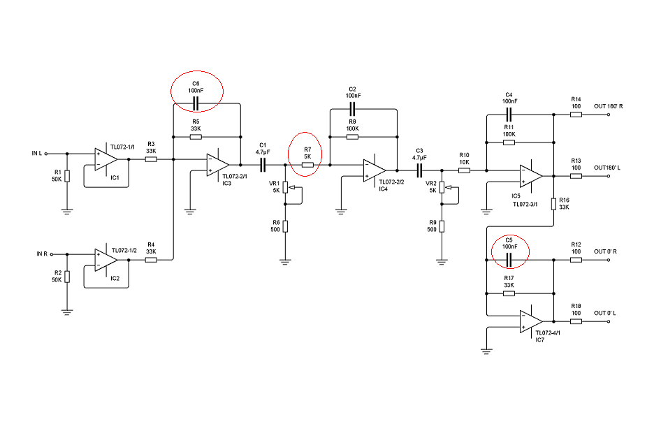
membuat filter subwoofer jbl suara mantap bass bulat menggelegarskema filter subwoofer menggunakan ic tl074 tl084 ne5532 tegangan 12 volt sampai 15 volt sime.

Skema filter subwoofer ic lm324 lasopachic
Berikut adalah skema pasang filter subwoofer pada sistem audio mobil: Pertama-tama, pastikan untuk mematikan semua sumber listrik dan putar volume stereo mobil ke posisi terendah sebelum memulai pemasangan filter subwoofer. Siapkan filter subwoofer yang akan dipasang. Filter subwoofer terdiri dari komponen-komponen seperti kapasitor, resistor.

Skema Filter Subwoofer Skema Dan Layout Pcb Power Amp PCB Circuits This is the circuit of
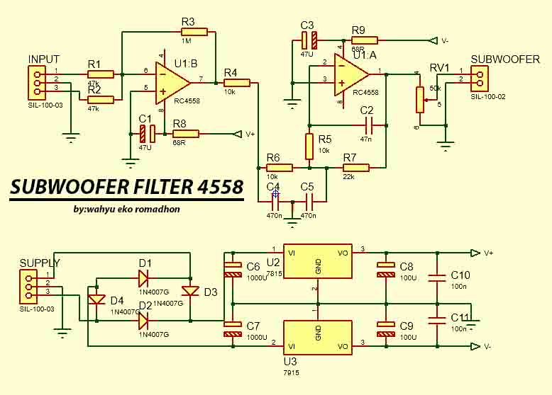
Skema rangkaian filter subwoofer sederhana yang bisa mudah dibuat karena komponen yang digunakan sangat mudah didapatkan. Komponen utama pada rangkaian ini adalah IC 4558d. IC ini adalah jenis IC op AMP yang umum digunakan untuk membuat tone control. Terutama menggunakan sistem tegangan simetris. IC ini memiliki penguatan sinyal lebih baik dari.
Skema filter subwoofer ic lm324 lasopachic
Dalam merangkai skema filter subwoofer sederhana, ada beberapa komponen lain selain komponen utamanya yang perlu dipersiapkan. Beberapa diantaranya, yaitu: IC 4558D, sebagai komponen utama. Resistor 1k , 10k, 2k2, 33K. Kapasitor 104 j atau ukuran 224j jika dikehendaki frekuensi yang lebih rendah. Tegangan 12 volt DC CT.

Subwoofer Filter NE5532 Schematic PCB Subwoofer, Subwoofer amplifier, Audio amplifier
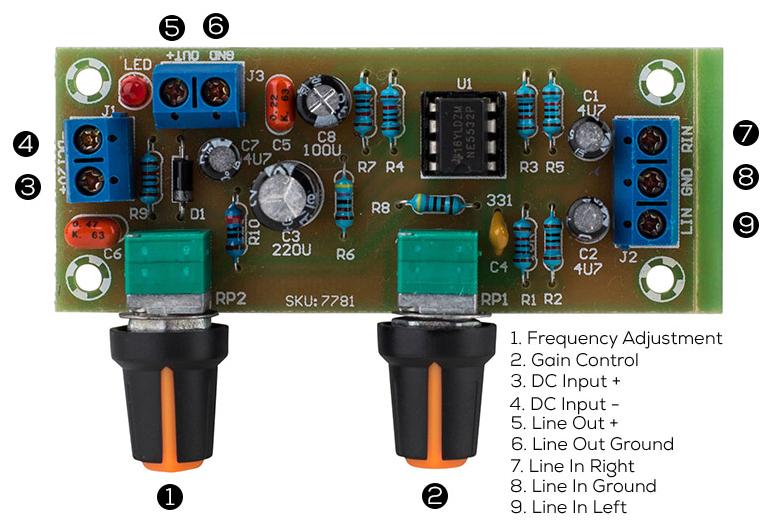
In this project I will show you how you can make a Low Pass Filter with 4558D IC for Subwoofer. Let's get started! Step 1: Watch the Video! This video gives you all the information you need to build your own Low Pass Filter. Step 2: Order Your Components. i ordered all the components from lcsc.com

skema subwoofer ic 4558 BLOGKAMARKU
The low-pass filter manages the upper limit of sound frequency (measured in Hz) produced by a subwoofer, effectively preventing any frequencies beyond the chosen value from being allowed to pass through. A subwoofer's frequency range works between 16Hz to 120Hz, while LFE (low frequency effect) mode enables full range and takes this to 200Hz.

Subwoofer Low Pass Filter using TL062 amplifier circuit schematic projects
Pada skema filter subwoofer Polytron PSW-500, resistor digunakan untuk mengontrol frekuensi cut-off dan membatasi arus yang melewati komponen lain. Kapasitor adalah komponen elektronik yang digunakan untuk menyimpan muatan listrik. Pada skema filter subwoofer Polytron PSW-500, kapasitor digunakan untuk memisahkan sinyal audio frekuensi tinggi.

Skema filter subwoofer ic lm324 bermocharter
Tapi kalau memang tetap ingin menambah filter subwoofer, maka cara koneksinya adalah paralel dengan turbo bassnya. Jadi in filter subwoofer paralel dengan in turbo bass dan out filter subwoofer paralel dengan out turbo bass. Tentu saja cara paralelnya menggunakan Resistor ya. Ikuti gambar skema diatas. Delete

Untuk Pemula (for Beginer) CARA MEMASANG FILTER SUBWOOFER
Low pass filter subwoofer using LM324. Last Updated on: February 9, 2024 by ElecCircuit.com. This is a low pass filter subwoofer using IC 324 and some other components. which is mr Kunal Banerjee sent to me to publish on our site.It is very useful Thank you very much.

CARA MEMBUAT FILTER SUBWOOFER non CT YouTube
Skema FILTER SUBWOOFER 12V DCDi video ini saya akan menjelaskan tentang Skema FILTER SUBWOOFER 12V DC atau rangkaian filter subwoofer sederhana dengan 1 tran.

Skema Pemasangan Filter Subwoofer Ruang Ilmu
Skema Filter Subwoofer Polytron. Banyak orang mencari berbagai jenis filter seperti rangkaian subwoofer Polytron Bazzoke, Bazooka, dan lain sebagainya. Jika Anda ingin merakit atau mempelajari rangkaiannya, silakan lihat skema yang terdapat pada contoh. Selain skema di atas, Anda bisa mencari dari sumber referensi lainnya seperti buku panduan.