
Etnik Sugitama Engineering Gambar Diagram Rangkaian Starter Star Delta Motor Listrik 3 Fhase
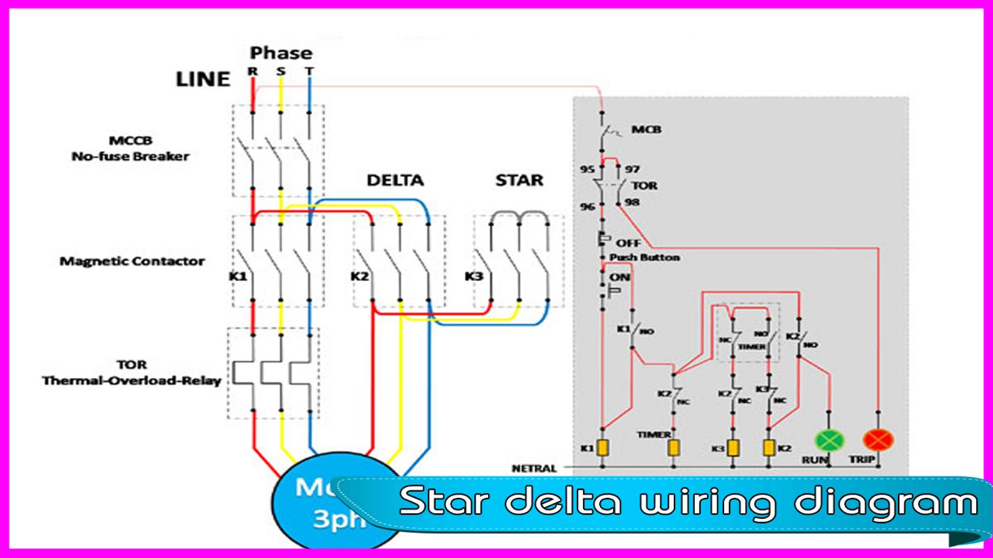
At its simplest, a Star and Delta Control Connection Diagram is a diagram that shows the relationship between the three phase supply and the electric load. The diagram shows the connections between the motor terminals and the overload, overload relay contacts, line voltage, and line current. This type of diagram is especially useful in.
Star Delta Starter Control Circuit Diagram Without Timer Wiring Digital and Schematic
So this time i want share my simple star delta circuit diagram completed with power and control line circuit.I hope it can be as basic reference for all electrician about star delta starter diagram. Star delta starter is a common used in domestic and industry sector to drive variant application such as chiller water pump,machinery,air-compressor and many more equipment.

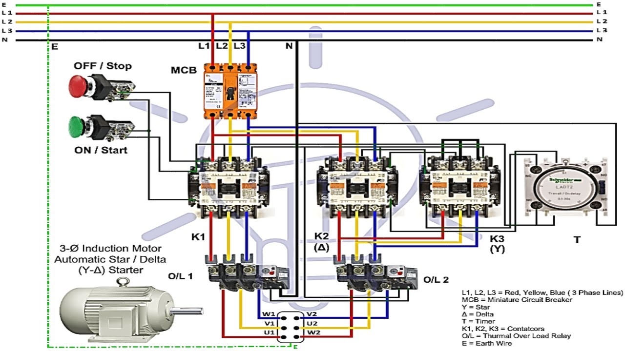
Automatic Star_ Delta Starter with timer for three phase induction motor/wiring Diagram YouTube
Working, construction, diagram. The star-delta wiring is an electrical circuit used in the motor power control in a three-phase power supply connection. This type of wiring connection helps in reduces the initialize high voltage in the motor windings, which helps reduce the high starting current in the starting of the three-phase induction motor.
Contrl Wiring Diagram Of Star Delta Starter StarDelta Three Phase Motor Starter Electrical Blog
The Star Delta Starter Control Wiring Diagram With Timer is a comprehensive guide to understanding the wiring of a single-phase motor control circuit. It includes components such as a timer, a contactor, overload protection and a three-phase motor. The diagram is divided into sections - each one representing a specific component.
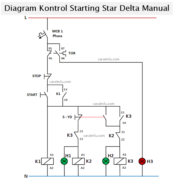
Rangkaian Star Delta Manual Dan Otomatis Cara Ilmu
Star Delta Starters Explained. How do star delta starters work for three phase induction motors and why do we use star delta starters. We cover the basic's o.

on video StarDelta Starter Explained (Power and control wiring) electrical and electronics
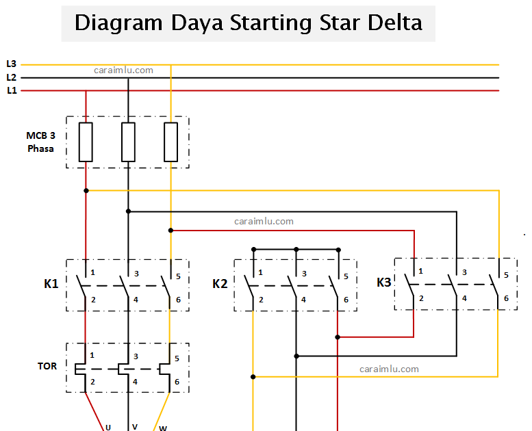
The wiring diagram for a 132kW star-delta starter used for a condenser pump is shown below: Star delta starter wiring diagram. The diagram can be divided into two parts: The power circuit & control circuit. Power circuit wiring. The power circuit of the starter consists of the following components:

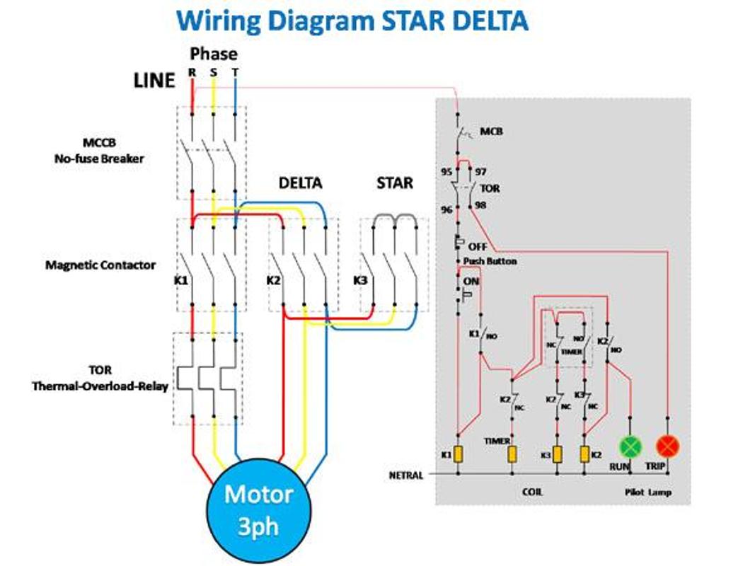
Wiring Diagram Rangkaian Star Delta
Star delta control circuit diagram with timer. Star delta connection with timer. The circuit diagram is drawn as pictured above. The dynamic circuit uses three contactors. The control circuit uses two push buttons to control the running and stopping of the motor. When we press the ON button, the motor will operate in star mode.
Star Delta Starter Wiring Diagram Explanation Wiring View and Schematics Diagram
Star Delta Control Diagram: Understanding the BasicsStar Delta Control is a widely used and well-known type of electrical control wiring diagram. This type of wiring is found in many industries, from factories and manufacturing plants to construction sites and other places where complex wiring and control systems are needed. The star delta.

A star delta starter wiring diagram 3 phase motor. star delta starter diagram with connection of
Star-Delta starter wiring diagram: Q1 serves as the main power supply switch that supplies electricity to the power circuit. The main circuit breaker Q1 connects or disconnects the main three-phase supply (L1, L2, and L3) to the motor terminals T1, T2, and T3. Fuses F1, F2, and F3 Protect the motor against overload.
Rangkaian Star Delta Manual Dan Otomatis Cara Ilmu
Principle of Working of Star Delta starter. The motor is first started by connecting its stator winding in a star configuration. The phase voltage in the star configuration is 1/ √ 3 of the phase-to-phase or line voltage. Thus, the voltage applied to the stator winding is about 58 % of the line voltage. The starting stator current reduces to.
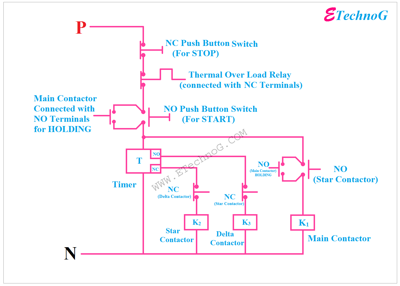
[Explained] Star Delta Starter Diagram Control and Power Circuit ETechnoG
Star-delta motor control power circuit. CAD drawing by ianjonas. Illustrated on the star-delta circuit diagram above, the three-phase line voltage L1, L2, L3 is supplied from the main circuit breaker down to the main magnetic contactor and finally to the three primary terminals of the motor coils U1, V1, W1. Meanwhile, the closing of the star.
Star Delta Wiring Diagram Star Delta Connection Star Delta Starter Control Wiring YouTube
The below image represents the power and control wiring of the star-delta starter. 1. OFF Stat ⇒ This is the off stat of the starter, all the contactors are in the OFF position. 2. STAR Stat ⇒ In this stat, Main and Star contactors are closed and Delta contactor is open. The motor is connected to STAR.
Simple Star Delta Wiring Diagram Wiring Diagrams Nea
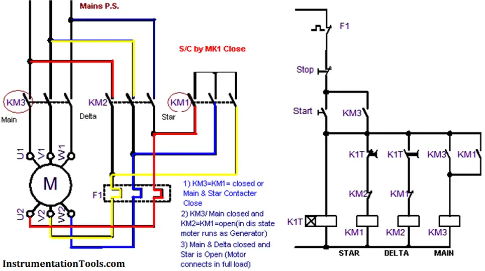
A Star-Delta starter is an electromechanical device used to start and control the speed of a three-phase induction motor. This starter employs the star-delta (Y-Δ) method for starting the motor, which involves changing the motor's winding connection from a Star configuration to a Delta configuration once the motor reaches a certain speed.

Implementation of PLC Based Star Delta Starter for Starting and Direction Control Of Three Phase
Star Delta Control Diagram is a powerful tool used to control electric motors in the industrial and commercial sectors. This diagram provides the user with an easy-to-understand graphical representation of the motor's power supply, allowing for quick and efficient troubleshooting and repair. The diagram is made up of three distinct sections.

cara membaca gambar rangkaian star delta Molly Hamilton
Creating a star-delta control circuit diagram involves understanding the components and connections required for the circuit. Here's a step-by-step guide to.

Star Delta Control Connection star delta power wiring diagram akr technical YouTube
The Star Delta Starter Control Circuit Diagram With Timer is a crucial component in the world of electrical engineering. It is a unique system that allows for the smooth and efficient control of three-phase motors, making it an essential tool for industrial and commercial applications. This innovative circuit diagram combines the benefits of.