
Basic PLC Ladder Programming Examples 16 PLC Tutorial Point
Ladder logic (also known as ladder diagram or LD) is a programming language used to program a PLC (Programmable Logic Controller). It is a graphical PLC programming language which expresses logic operations with symbolic notation. Ladder logic is made out of rungs of logic, forming what looks like a ladder - hence the name 'Ladder Logic'.
Sample PLC program in ladder diagram. Download Scientific Diagram
In this ladder logic example, there are two inputs. "Start button" or PLC input I0.0. "Stop button" or PLC input I0.1. The start button will activate the relay, or ladder logic relay M10.0. When the start button is released, the relay will still be activated, because of the latch in ladder rung 2.

MEMBUAT PROGRAM LAMPU FLIP FLOP MENGGUNAKAN PLC LADDER SIMULATOR YouTube
Ladder Logic. Ladder logic is basically a program that is represented by a graphical diagram, which is based on a circuit diagram of relay logic. This program contains two vertical lines called 'rails' and horizontal lines called 'rungs' which makes it look like a perfect ladder. The graphical representation of an ladder logic program.

MEMBUAT RANGAKAIN SISTEM KONTROL CONVEYOR DI PLC LADDER SIMULATOR YouTube
Secara umum PLC memiliki metode logika yang sama, apa pun yang membedakan adalah tentang notasi pengalamatannya. Instruksi dan fitur dalam pemrograman PLC akan dibahas lebih lanjut pada artikel berikutnya. Logika dasar pemrograman PLC dengan menggunakan bahasa ladder diagram, meliputi logika AND, OR, dan NOT beserta penerapannya.
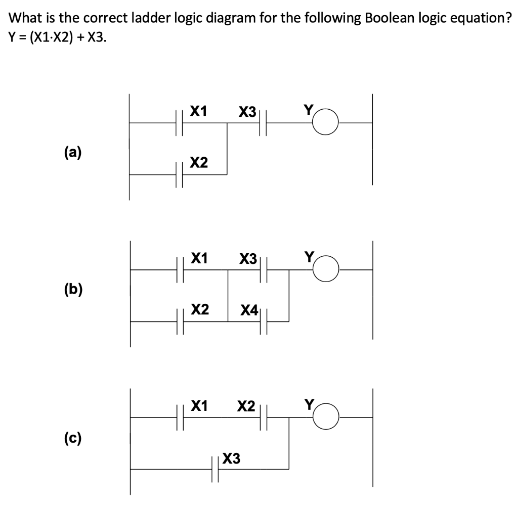
Ladder Logic Diagram Examples / Ladder Logic Basics Ladder Logic World / In the united states
kelasplc. April 23, 2022. Simbol Ladder Diagram PLC - Simbol simbol ladder diagram yang di gunakan dalam pemrograman ladder diagram sebenarnya mirip dengan sirkuit kontrol logika relai tradisional. Jika Sahabat memiliki pengetahuan dasar tentang rangkaian listrik maka memulai pemrograman dengan bahasa pemrograman Ladder diagram sangatlah mudah.
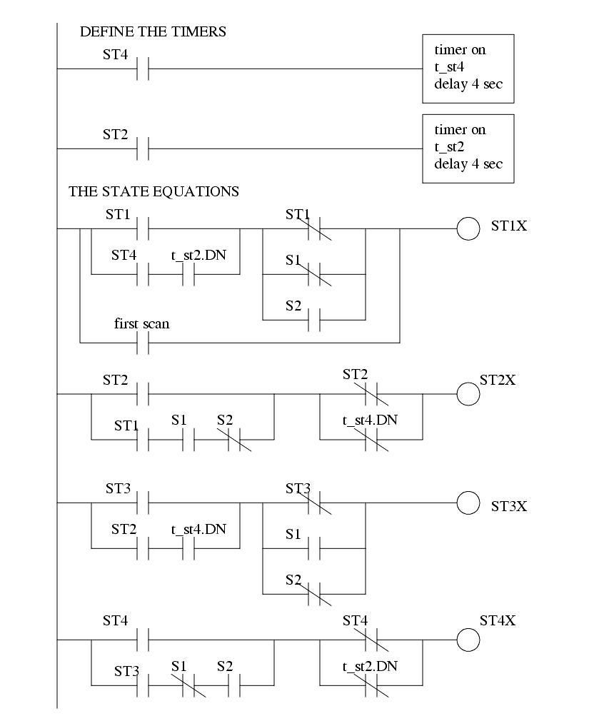
Plc ladder diagram examples polean
The Ladder Diagram's name is derived from its ladder-like appearance, with rungs symbolizing individual logic conditions and coils representing outputs. For engineers familiar with relay-based control systems, the Ladder Logic's graphical representation is both intuitive and reassuring. As control and automation engineers, our expertise in.

Contoh Soal Ladder Diagram Plc
Contoh Soal PLC. Contoh Soal PLC. Yopi Arisandi. See Full PDF Download PDF. See Full PDF Download PDF. Related Papers. About PLC. Muhammad Shofwan.. Mengetahui dan dapat menggunakan piranti dari ladder diagram. 2. Alat/Bahan : PLC, PC, Kabel, Tombol Push-Button dan indicator lampu. 3. Percobaan : a.
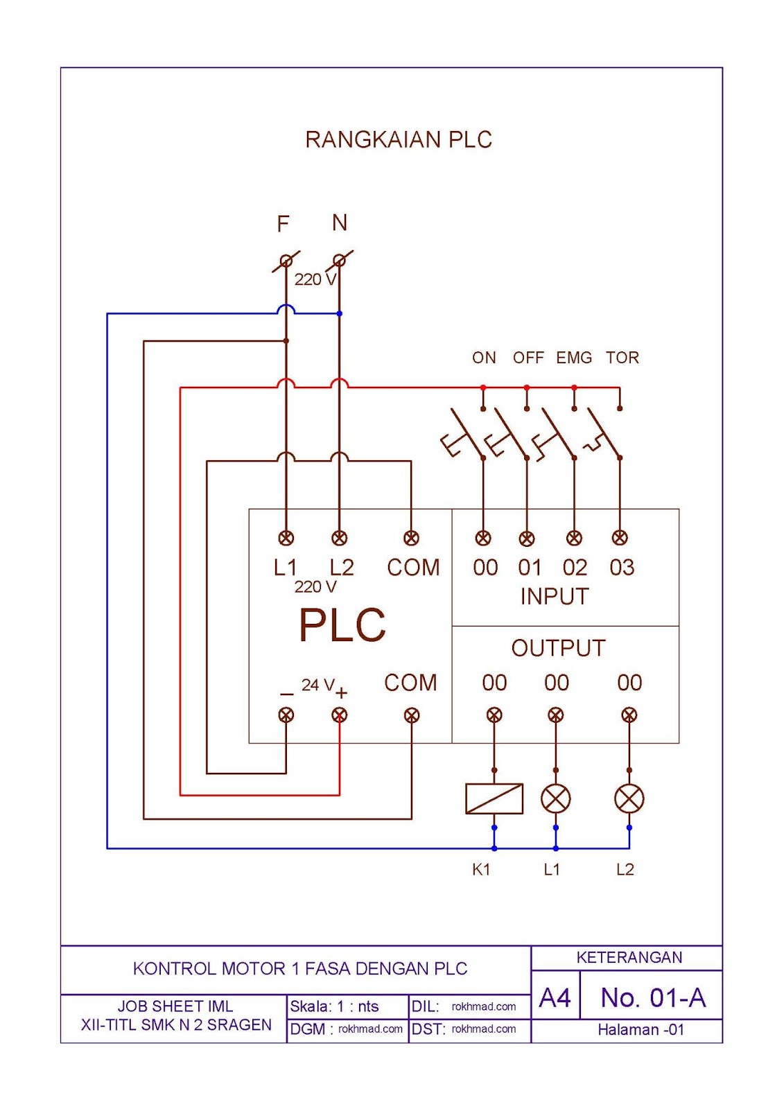
Contoh Soal Ladder Diagram Plc Terbaru
Instruksi Dasar Pemrograman Diagram Ladder. Materi PLC; 24 September 2019, 09.59;. Simbol-simbol diagram ladder dan alamat memori digunakan untuk membuat program ladder. Beberapa simbol diagram ladder dasar mencakup Input (kontak NO), Input (kontak NC), dan Output.. Contoh Penggunaan Diagram Ladder. Instruksi Dasar Pemrograman Ladder.
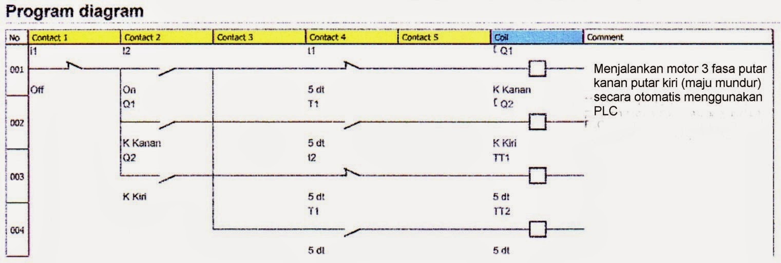
Macammacam Contoh Sederhana Ladder Diagram PLC Siaran Dunia
Contoh input dan output. Dalam PLC Ladder Diagram, peranan input dan juga output bisa dikatakan sebagai kunci keseluruhan.Untuk input, acuannya pada saklar atau dikenal juga sebagai push button.Kemudian bagian output mengacu pada lamp, load, dan disebut juga sebagai coil.. Semuanya memegang peranan penting dalam pemrograman. Pada bagian input, ada dua hal yang harus dipahami, yakni NO atau.

Contoh Soal Ladder Diagram Plc
Ladder Logic (LAD) for S7- 300 and S7-400 Programming Reference Manual, 04/2017, A5E41524738-AA 3 Preface Purpose This manual is your guide to creating user programs in the Statement List programming language Ladder Logic. The manual also includes a reference section that describes the syntax and functions of the language elements of Ladder Logic.

Contoh Soal Tes Plc Dan Penyelesaiannya Materi Soal
Pengertian Ladder Diagram Pada PLC. Pada kesempatan kali ini Kelas PLC akan menjelaskan kepada Sahabat mengenai Pengertian Ladder diagram dalam pemrograman PLC dan bagian bagian pada Ladder Diagram. Ada beberapa bahasa pemrograman standar yang ditentukan untuk Programmable Logic Controller (PLC). Beberapa Bahasa standar yang diterima secara.

Contoh Soal Ladder Diagram Plc
PLC ladder diagram name praktikum tujuan mengetahui prinsip kerja dari pemrogram ladder diagram. mengetahui dan dapat menggunakan piranti dari ladder diagram.. Contoh Soal PLC - PLC. PLC. Course. Elemen Mesin (TIN04220) 6 Documents. Students shared 6 documents in this course. University Universitas Pamulang. Academic year: 2014/2015.
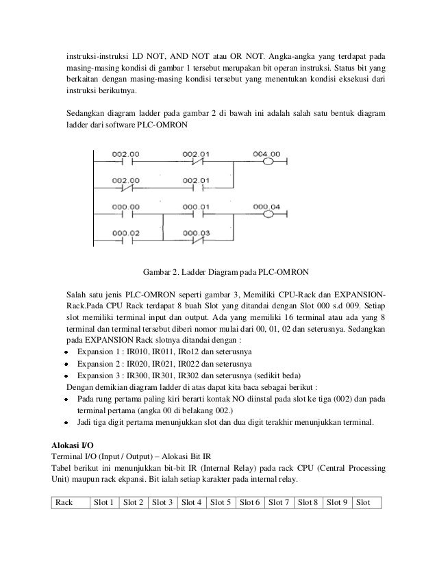
Contoh Soal Tes Plc Dan Penyelesaiannya Materi Soal
dibuat dengan diagram tangga dapat diprogram pada PLC maka beberapa ketentuan yang harus diikuti antara lain : • 1. Jumlah kontak untuk relay-relay input output, relay-relay bantu, timer, counter, dapa digunakan sesuai dengan kapasitas maksimum yang disediakan oleh PLC. • lakukan dengan sesederhana mungkin, sehingga efisiensi kerja

CARA MEMBUAT LADDER DIAGRAM PLC YANG BENAR AWAS!!! NO NC TERBALIK YouTube
The PLC Ladder Logic programming example that I am about to share is used for the production monitoring. This project can be used in all those areas where you need to count the items. It can be used on conveyor belts for counting bottles, boxes, etc. As this project is based on the counting, so in this project the counter will be used.

Contoh Soal Ladder Diagram Plc Terbaru Riset
If the XIC is False, the PLC aborts this rung. Step 3 - The hypothetical current goes to the next instruction. Repeats Step 2 until the rung is completed. Step 4 - The PLC moves to the rung below. Ladder Logic PLC Programming XIC = OFF Example. In the example above, the XIC Instruction is tied to the bit "Condition1".
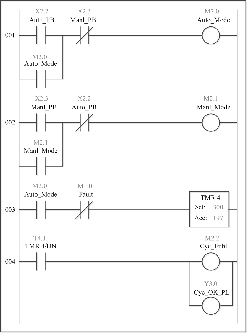
Design a plc ladder logic program to control the operation of an alarm bobnimfa
Conclusion: The above explained ladder logic for quiz program is for example only. We can use this example program to understand the working of Push Buttons, memory bit and Interlocking in AB PLC. If you liked this article, then please subscribe to our YouTube Channel for PLC and SCADA video tutorials.