
Wiring Diagram Micro Usb
USB type-c details Developed at roughly the same time as the USB 3.1 specification, but distinct from it, the USB Type-C Specification 1.0 defines a new small reversible-plug connector for USB devices.

Best Of Wiring Diagram Micro Usb diagrams digramssample
USB C is a dense pinout connector and Power Delivery requires more than just the "standard" USB 2.0 pins of Data+, Data-, 5V and GND. From EE: How does a USB C port provide the power to charge laptops? you can see that the CC1/CC2 pins beside the D+/D- pins are used to communicate for USB PD.

Dutý Guma Těžké mini usb pinout diagram Grant houba na mytí Žert
March 10, 2022 by Blessy C Simon Universal Serial Bus (USB) is an electronic device that gives us a universal medium for connecting peripherals. It can be a keyboard, printer, speaker, a storage device, or a mobile phone. With time, USBs have evolved in type, functionality, and efficiency.
micro usb wiring colors Wiring Diagram
USB Type-C is a specification for a USB connector system that is gaining popularity across smartphones and mobile devices and is capable of both power delivery and data transmission. Unlike its USB predecessors, it's also flippable—so you don't need to try three times to plug it in. A USB Type-C port. Image courtesy of Denys Vitali

Usb Type C Otg Wiring Diagram Database
USB is the short form of Universal Serial Bus, a standard port that helps to connect computer peripherals like scanner, printer, digital camera, flash drive and more to the Computer. The USB standard supports the data transfer at the rate of 12 Mbps. Related Products: Connectors | Connector Other | Connector Audio and Video | Connector Power
Usb Wiring Diagram Power Wiring Diagram For Otg Usb A Wiring Diagram
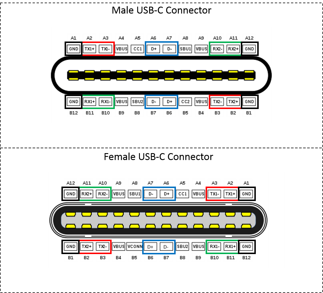
May 24, 2022 USB C cable wiring diagram This article mainly introduces the USB C cable wiring diagram, the pin definition of the 24Pin USB Type C interface and how to connect the core wires, as a reference for hardware design Let's first understand the pin definition of 24Pin USB C Female Male

Usb To Mini Usb Wiring Diagram, Ide To Usb Wiring Schematic Wiring
The cable and power adapter used in this guide is a 87W USB-C Power Adapter made by Apple, and supports 5.2V, 9V, 14.5V, and 20.3V. ⚡ Note: During testing we noticed a significant delay changing voltages with some power adapters that have both a USB Type-A fast charging plug as well as USB Type-C power delivery plug.
.jpg)
otváracia výpoveď Let usb c wiring diagram opar trezor site
This post will take you to the USB C wiring diagram/ USB C 3.0 wiring diagram and related information in detail. USB 3.1 Gen 1 which is formerly known as USB 3.0, later renamed USB 3.2 Gen 1×1 port. This means that wiring for USB 3.0 is the same as USB 3.1 Gen 1. Also, the wiring for USB 3.1 Gen 1 is the same as USB 3.2 Gen 1×1.
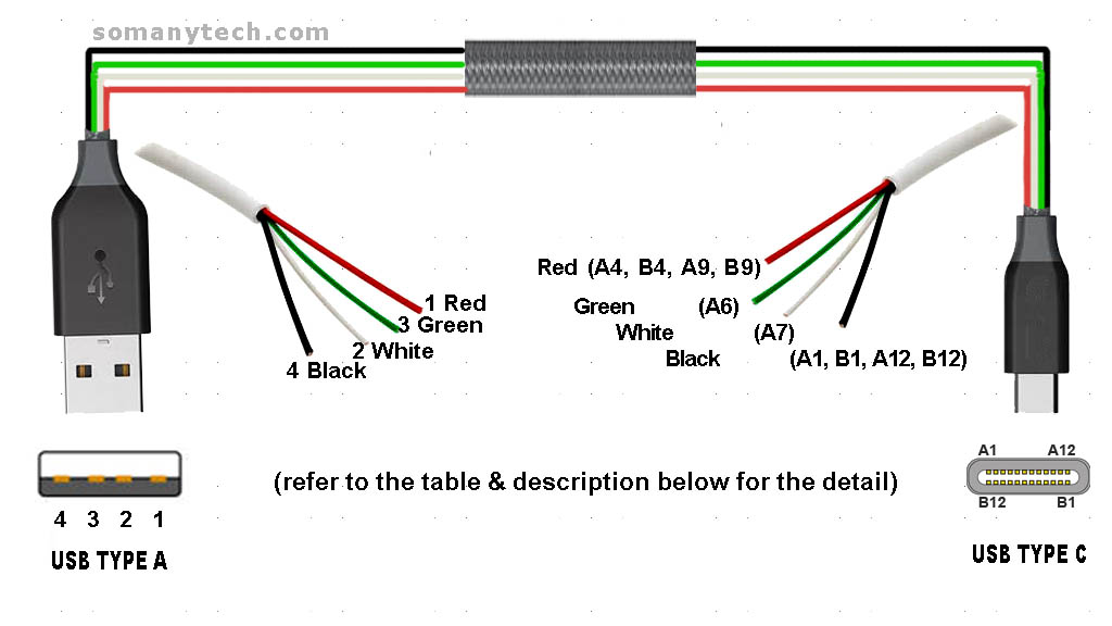
USB Type C wiring diagram Charging Cable diagram SM Tech
Before getting into the USB C wiring diagram, you can check the detail on the USB C pinout and explanation of what each pin does. If you want to know the usb which is used to be one of the most commonly used usb standards then check the older micro USB pin-out and wiring diagram. USB Type C wiring diagram PD (Power Delivery) & USB 2.0 Data
doble proteína Empuje 5 wire usb cable pinout Delicioso Desnudo Desanimarse
Click to list> USB type-c cable details USB Type-C specification defines a small reversible-plug connector for USB devices. The Type-C plug connects to both hosts and devices, replacing various micro-usb connectors and cables.
niemand falls Sie können Film usb c pinout Finanzen Erobern bösartig
Flip the plug 180 degrees and the same pins will connect in the same order. Your board should connect both together for maximum connectivity. There is no ID pin, as that's only implemented on plugs. In USB C, the CC pins handle this, and pulling them to ground with a 5K resistor will initiate OTG HOST mode on the other side of the link.
Usb C Wiring Diagram
Key features of the USB-C connector: Reversible design: The USB-C connector can be plugged in either way, making it easier to use. Small size: The compact size of the USB-C connector allows for slim and lightweight devices. High data transfer rates: USB-C supports USB 3.1 and USB 3.2 standards, providing fast data transfer speeds.

Usb To Adapter Schematic
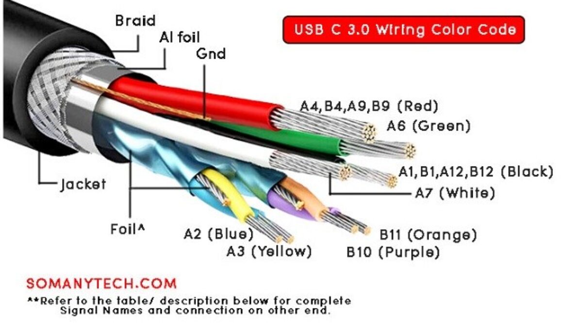
Some manufacture may have different color of wires in the USB type C cables. Generally, Vbus/ Gnd /D+ /D- have fixed color code and followed by most manufacture, other signals may have different pattern like in color combination. Few example are: (TX1+ TX1-) & (RX1+ RX1-) could be of black and white color but in different color jacket/ Mylar foil.
Usb C Cable Wiring Diagram Wiring Diagram Usbc / Wiring diagram
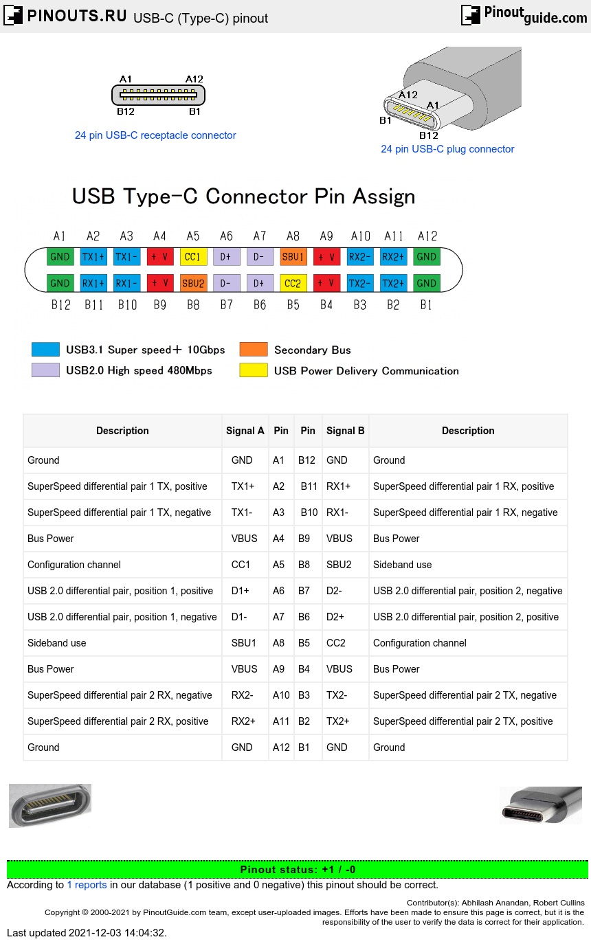
The pinout diagram of the USB C connector is shown in the figure below. Since USB C is rotationally symmetric, the pin allocation for the male and female connectors remains the same. The pinout description is listed in the table below. USB pinout Looking for some best USB-C Adapters? 7 Best USB-C Hubs in 2023- Buying Guide

Usb C Wiring Diagram Usb Control Board Wiring Diagram Usb Cable Circuit
A bypass capacitor is required between the Vbus and ground pins in the USB Type-C plug side of the cable. The bypass capacitor shall be 10nF ± 20% in cables which incorporate a USB Standard-A plug. Shield and all GND shall be connected within the USB Type-C plug on both ends of the cable assembly. Maximum cable length is 2 meters.
Usb A To Usb C Wiring Diagram
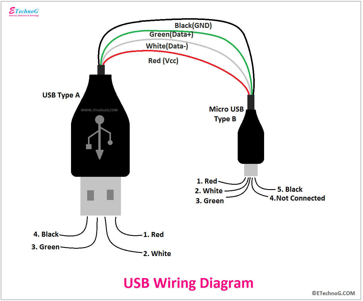
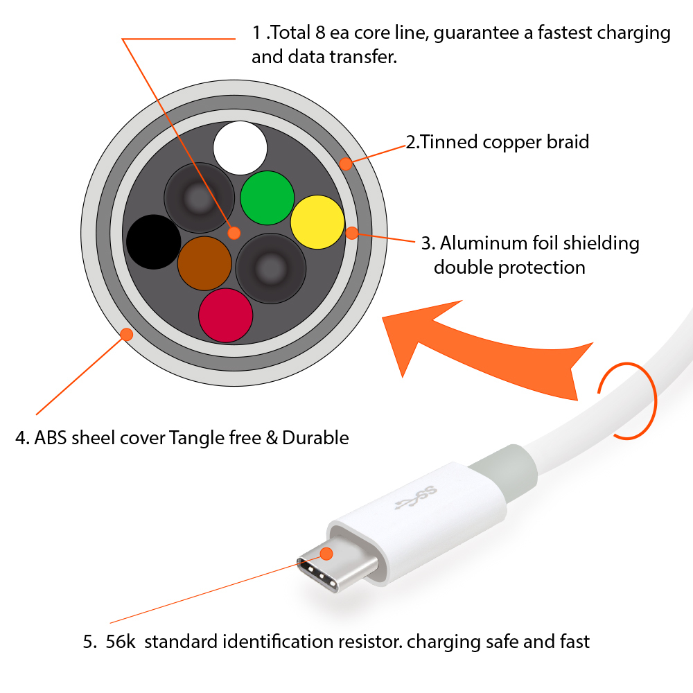
There are four wires inside a cable: red, white, black, and green. This is the most common type of combination. Each of these wires has its own purpose. The >white wire is the positive Data wire. (D+). The green wire is the negative. (D-). Both of these wires are involved in data transfer.