6 Terminal Ignition Switch Wiring Diagram Briggs And Stratton 6
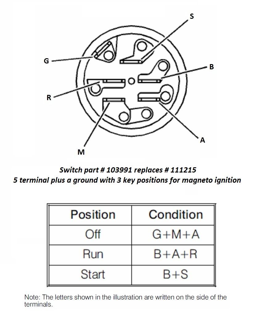
Let's use your continuity tester. Ask Your Own Small Engine Question. ok. Technician: Donald. Look at the bottom of your ignition switch. Each one of your seven prongs will have an identifying letter either stamped into it, or stamped next to it. Look for a ( B) and a ( S ). Ask Your Own Small Engine Question. ok.

6 Prong Ignition Switch Wiring Diagram Wiring Diagram Schematic
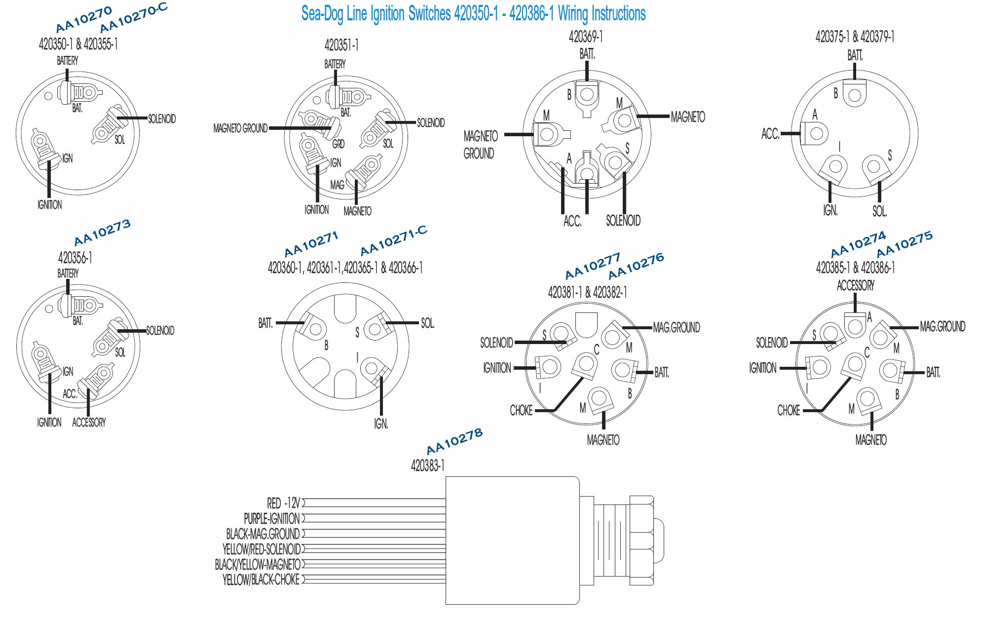
Understanding the wiring diagram for a 7 prong ignition switch is essential for troubleshooting, repairing, or replacing the switch. A 7 prong ignition switch typically consists of seven terminals or prongs labeled with different letters, such as B, M, S, I, R, A, and C. Each terminal has a specific function and connects to different parts of.

Ignition Switch 3497644 Wiring Diagram Previous Wiring Diagram
If you are looking for A2 On Mtd Ignition Switch Wiring Diagram you've visit to the right page. We have 35 Pics about A2 On Mtd Ignition Switch Wiring Diagram like 5 prong ignition switch wiring diagram, 5 Wire Ignition Switch Wiring Diagram and also Mtd Ignition Switch Wiring Diagram - Wiring Diagram. Here you go:

6 prong ignition switch wiring diagram Wiring Diagram
Having a riding lawn mower with a 7 prong ignition switch can be a great way to make mowing your lawn easier. However, if the switch isn't working properly, it can be difficult to know what to do. Testing the riding lawn mower 7 prong ignition switch is an important step to ensure that it is working correctly and that your mower is in good running order.
5 Pin Ignition Switch Wiring Diagram
Prong Ignition Switch Diagram: A Comprehensive Guide. Understanding the wiring and connections of a 7-prong ignition switch is crucial for anyone working with automotive electrical systems. The ignition switch is an essential component that controls the flow of electricity from the battery to the starter motor, allowing the engine to start and run.

5 Pin Ignition Switch Wiring Diagram
A standard ignition switch, like the MTD 7 Pin, is made up of five or six pins. The diagram allows you to connect wires from different parts of the vehicle - such as the starter motor, an alternator, or the distributor - with the appropriate pin on the switch itself. The wiring diagram shows which wire goes to which pin on the actual switch.
5 Prong Ignition Switch Wiring Diagram
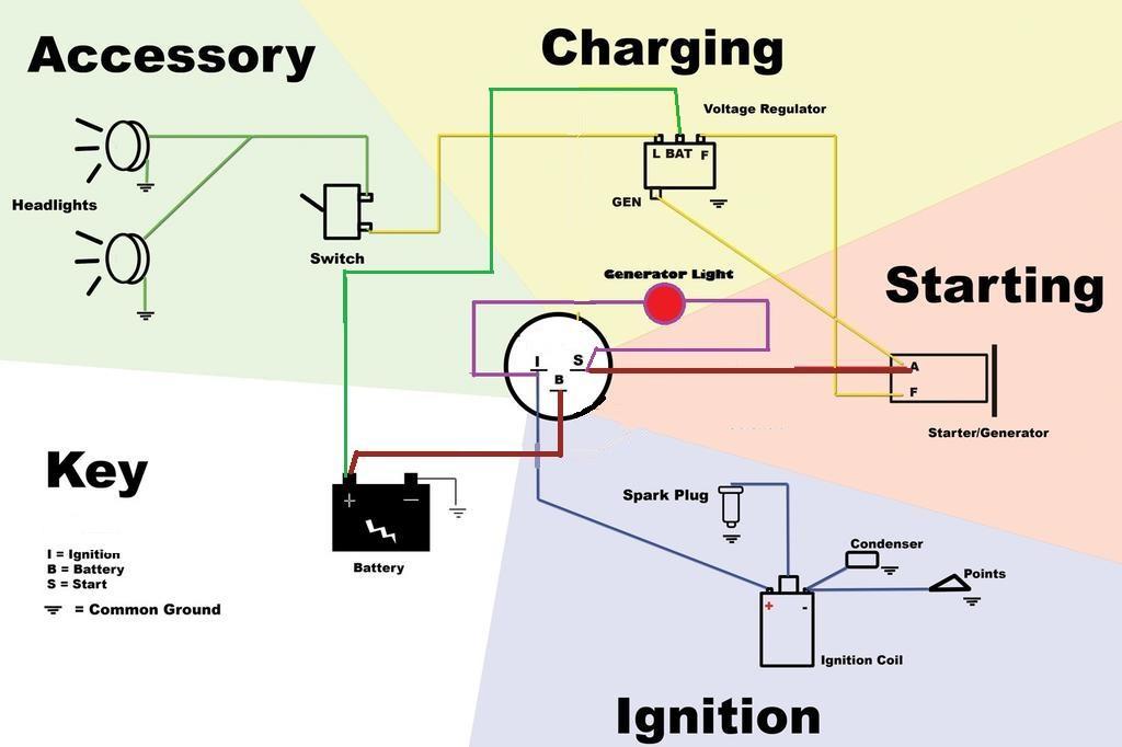
Step 1: Obtain a circuit diagram. Step 2: Locate all components that need wiring. Step 3: Connect the switch to ground. Step 4: Connect the switch to the Solenoid. Step 5: Wire the magneto to the switch. Step 6: Provide voltage by connecting the battery. Step 7: Connect the accessories/ lights.
7 Prong Ignition Switch Wiring Diagram Wiring Harness Diagram
A 7 prong ignition switch is a specific type of switch that has seven terminals or connection points. The seven terminals on a 7 prong ignition switch are labeled and each serves a different purpose. Terminal 1 is typically used for the battery power supply, while terminal 2 is for the ignition system. Terminal 3 connects to the vehicle's.
7 Prong Ignition Switch Wiring Diagram Wiring Harness Diagram
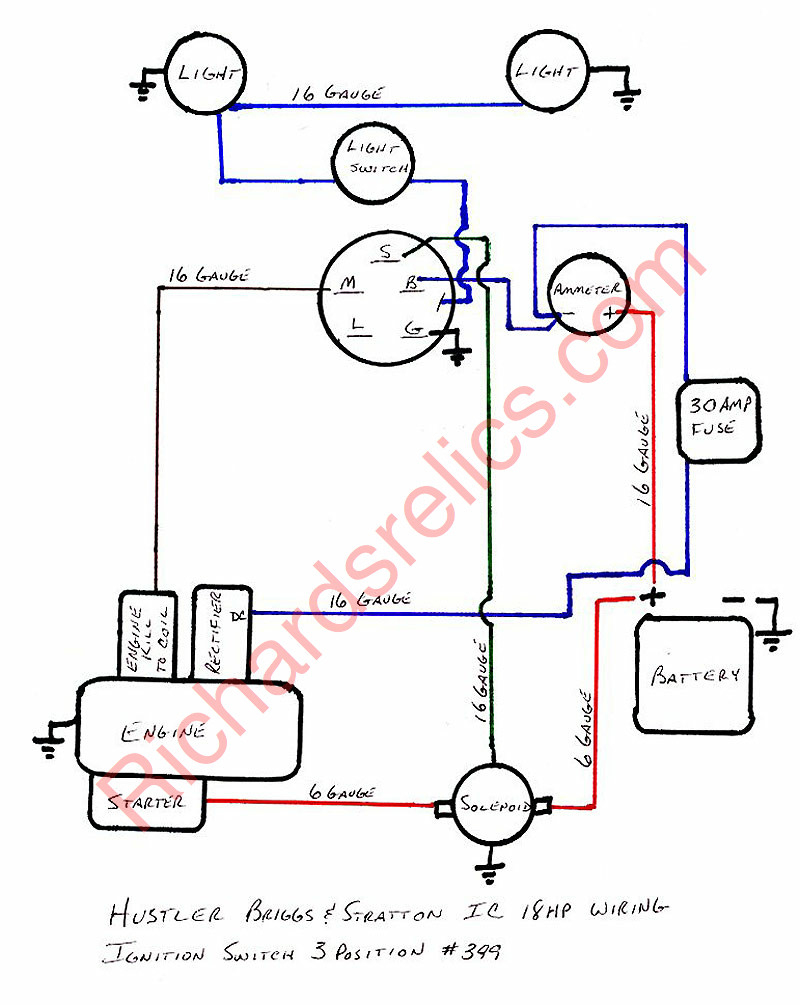
Connect Wires. Start with the positive lead from the car battery going to the ignition switch. It's often a red wire that's thick and constantly energized. Fit the terminal end from the power lead wire and secure it. Connect this lead to the BATT terminal of the switch. Connect the accessory wire to the ACC terminal next.
Wiring Diagram For Lucas Ignition Switch Wiring Diagram and Schematic
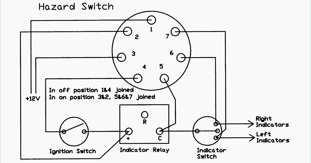
A 7 prong ignition switch wiring diagram will usually have seven different connections, labeled as 1-7. These connections, when wired together, create the power supply to the vehicle's engine. Additionally, there may be a few additional connections, such as ground terminals and a power terminal.
7 Prong Ignition Switch Wiring Diagram Wiring Harness Diagram
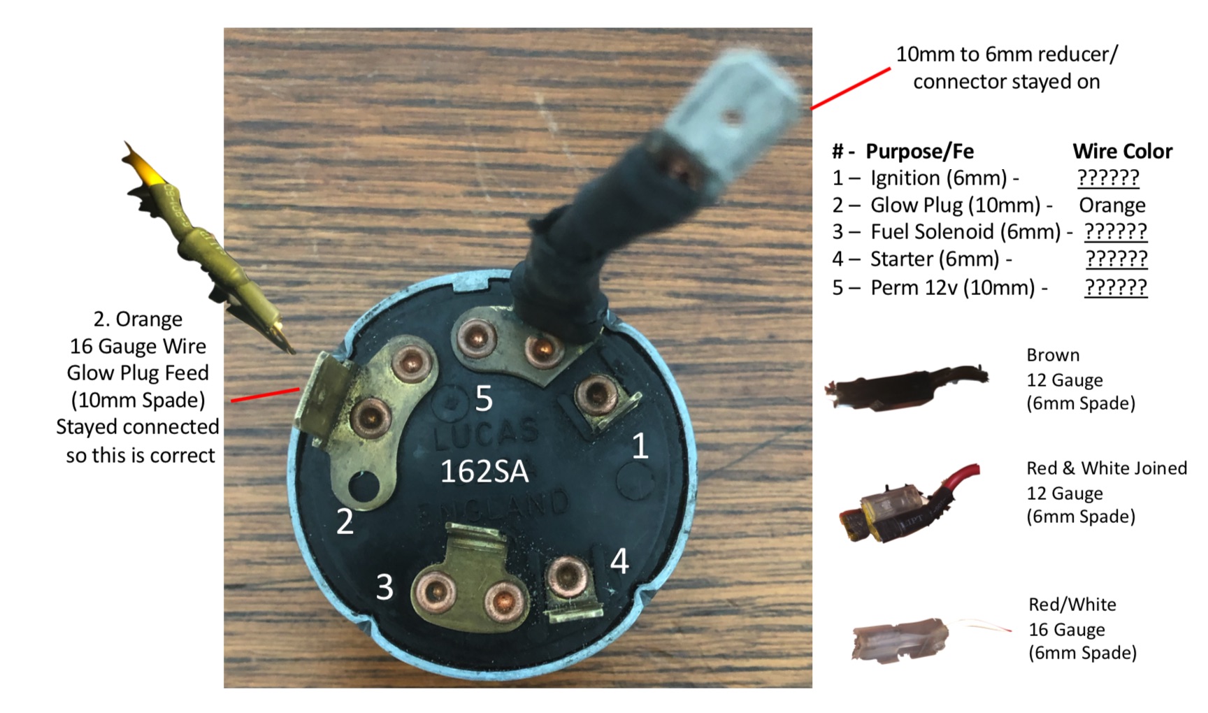
Two pictures are attached - the old wiring into the old ignition and the new ignition. Old ignition had three connections: -IGN. -ST. -BAT. There were four wires going into the old ignition - here is what I believe they connect to: -green - volt meter.


