
Cat5 Wiring Diagram Series A
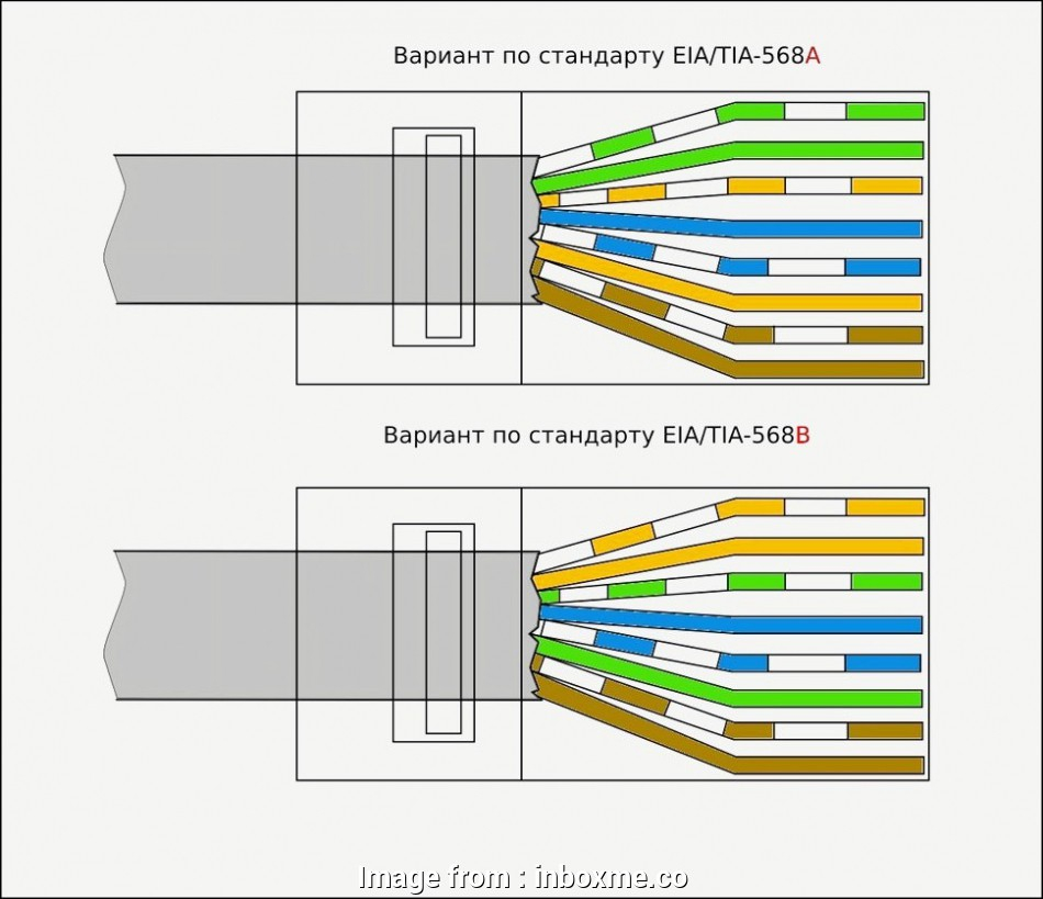
Using the proper cat5 wiring diagram b is crucial for achieving maximum signal quality across the cable. If the cables at each end don't follow the same wiring standard, the connection may not work at all. T-568A The T-568A standard specifies the following cat5 wiring color code order:

Cat 5 E Wiring Diagram
A Cat5 wall plate wiring diagram is a visual representation of the wiring setup for a Cat5 wall plate. The Cat5 wall plate is a networking jack that allows you to connect Ethernet cables to your wall, providing a convenient and organized way to connect devices to your network.

Cat5e Wiring Diagram Australia Cable A Cat 5 Connectors Data Wire New Wiring diagram, Diagram
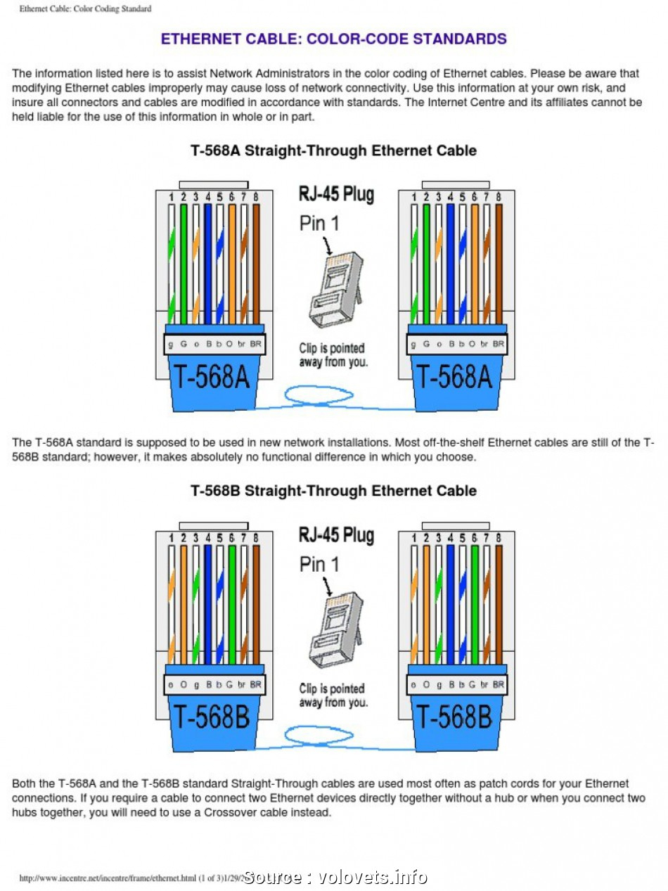
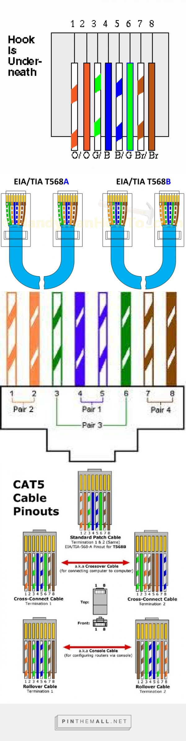
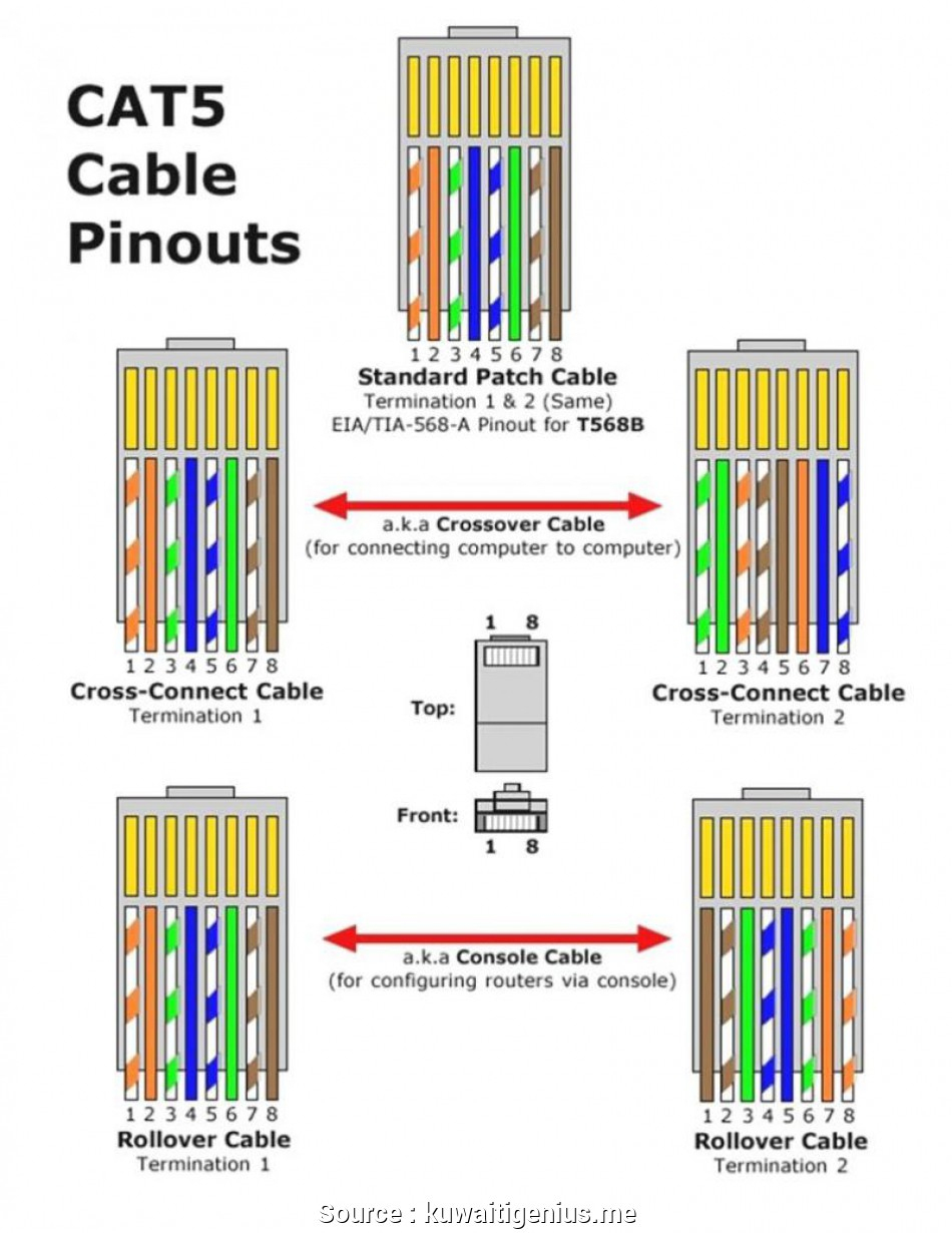
There are three popular wiring patterns for Cat5e and RJ-45 cables: 568A, 568B, and a crossover cable with 568A on one end and 568B on the opposite end. Functionally there is no difference between a straight through 568A to 568A cable and a straight through 568B to 568B cable.
Cat5 Male Connector Wiring
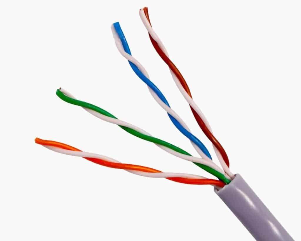
Category 5 cable ( Cat 5) is a twisted pair cable for computer networks. Since 2001, the variant commonly in use is the Category 5e specification ( Cat 5e ).
Cat5 Wiring Diagram A Complete Tutorial EdrawMax
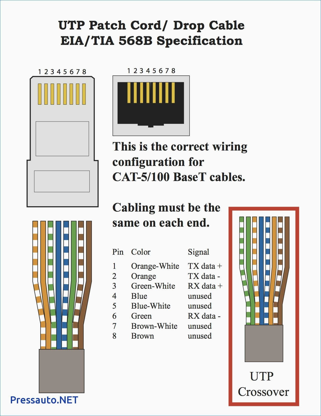
Cat5 Network Cable Wiring Diagram Standard July 20, 2017 Networking ISSUE: what is the proper sequence for the colored wires in a PSU Cat5 network cable plug? RESOLUTION: We use the T-568B standard for network cables. As shown in the image above, hold the RJ-45 plug with the tab facing down, and arrange the wires:

Cat5 Cable Wiring How to Crimp Your Own Custom Cables / If you're wondering
CAT-5 Wire Pairs. The four wire pairs in a CAT-5 cable are distinguished by the color of their insulation. The four colors are (in order). the hook will be underneath and the contacts (pins) will be on top. The diagrams below and the wall jacks follow this standard. Figure 1: RJ-11 Click on picture to switch cable types : Figure 2: RJ-45
cat5 to rj11 wiring diagram
The Cat 5e cable, also known as Category 5 enhanced cable, is an upgraded version of the Cat 5 cable and is widely used for Ethernet connections. It provides a more robust and faster network performance compared to its predecessor. Understanding Cat 5e wiring diagrams is crucial for a successful installation.

Cat5 Cctv Wiring Diagram Free Wiring Diagram
Cat 5 or category 5 is a network cable that consists of four twisted pairs of copper wire terminated by an RJ-45 connector. It is also known as an Ethernet cable or LAN cable. A Cat 5 cable is depicted in the image. Cat 5 cable is used in residential and business networks to transmit data at rates of up to 100 Mbps.
Cat5e Wiring Diagram Wiring Diagram
A Cat 5 cable diagram is a drawing that depicts how the Cat 5 cable is physically laid out. It's composed of two distinct parts: the pinout and the wiring schematic. The pinout is a map that shows which pins on the connector match up to which wires in the cable. The wiring schematic is a diagram that shows exactly how the wires are connected.

Att Uverse Cat5 Wiring Diagram Free Wiring Diagram
A Cat5 telephone wiring diagram is a visual representation of how to wire a telephone system using Cat5e or Cat6 Ethernet cables. It shows the connections and pathways that allow voice signals to be transmitted over the network cables. These diagrams are used by technicians or DIY enthusiasts to ensure the correct installation and setup of.

Cat 5 Wiring Diagram Pdf
Cat5e Wiring Diagrams. A Cat5e wiring diagram will show how Category 5e cable is usually comprised of eight wires, which have been twisted into four pairs. The twists counteract interference. A Cat5e cable has improvements in its twist ratio when compared to a Cat5. This enhanced cable is used for a variety of installations, including crossover and patch cabling.
Cat 5 Wiring Diagram Printable Wiring Diagram
Dive into the world of using cat 5 cable diagram. Understand how these tiny lines of wire power our digital world, and learn how to use them effectively.
Cat5 Plug Wiring Diagram
The Cat5 wiring diagram provides a step-by-step guide, showing which wires go where and how to terminate them. Properly wiring your Ethernet network with Cat5 cables is essential for optimal performance and reliability. Whether you're a beginner or a seasoned network engineer, understanding the Cat5 wiring diagram is a must..

Cat 5 Connector Wiring
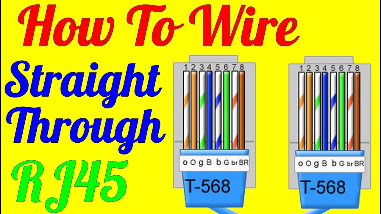
Flatten the wires out as much as possible, because they need to be very straight for proper insertion into the connector. Step 3, hold the cable ends and place the wires in orders from left to right according to T568A or T568B wire scheme. Step 4, insert the wires into the RJ45 connector. The wires must be sequenced in the same order of step 3.

[DIAGRAM] Cat5 Wiring Diagram Printable
This CAT5 wiring diagram and crossover cable diagram will teach an installer how to correctly assemble a CAT-5 cable with RJ45 connectors for regular network cables as well as crossover cables. Please note that these instructions are the same for CAT-6 cable and and other type of 4 twisted pair network cable. Please also note that in this.
Cat 5 Wiring Diagram Pdf Cadician's Blog
Cat 5 wiring diagrams are a set of diagrams that define the configuration of cables and wires used to create a local area network (LAN) connection. CAT 5 cables are the most popular type of cables used in home networks, due to their low cost, easy installation and higher bandwidth capacity.