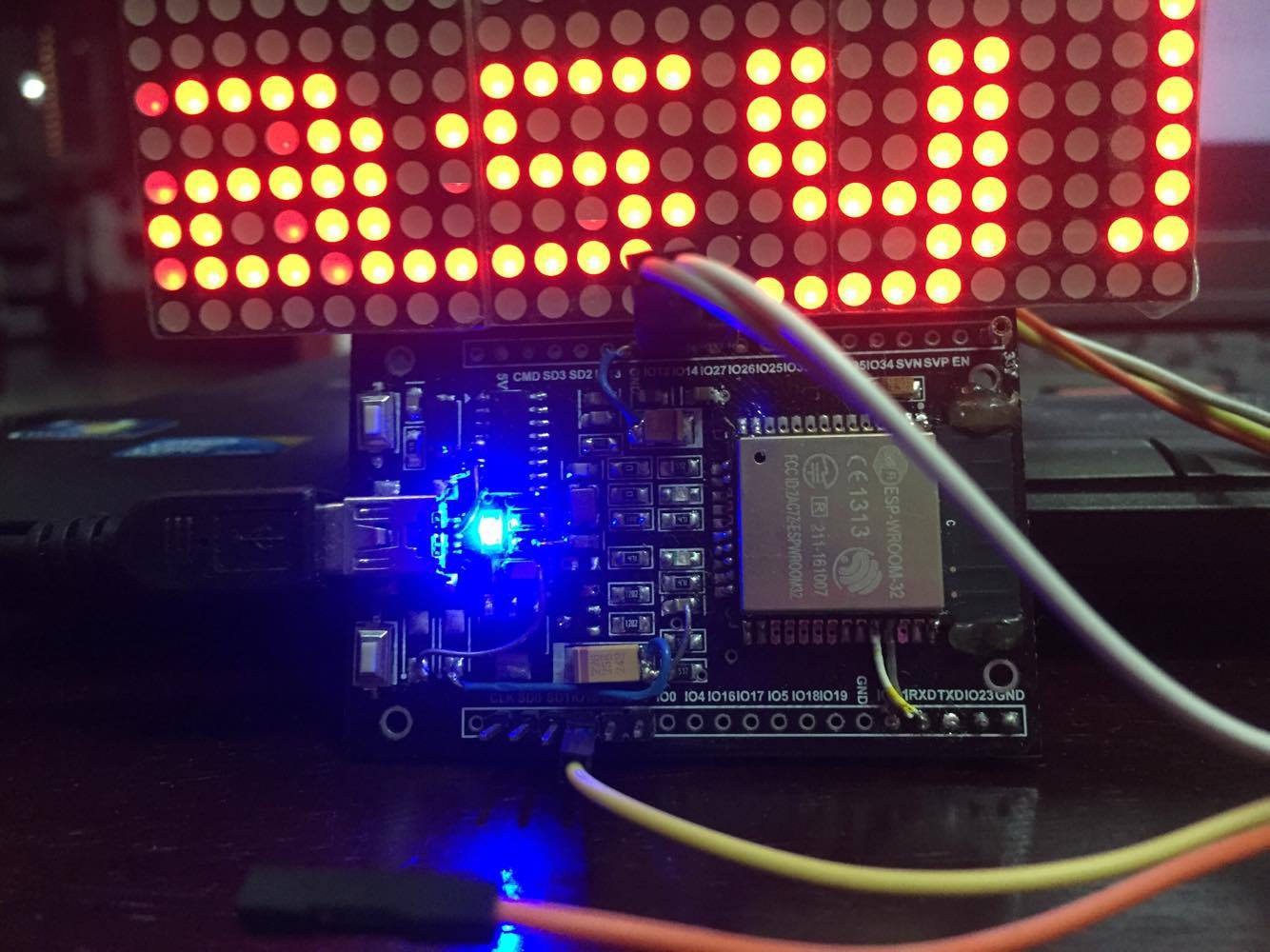
Demo 5 How to use Arduino ESP32 to display information on SPI LED matrix
Dan Maloney. January 6, 2024. It's not entirely clear why [Advanced Tinkering] needs a 50,000-volt power supply, but given the amount of work he put into this one, we're going to guess it will.
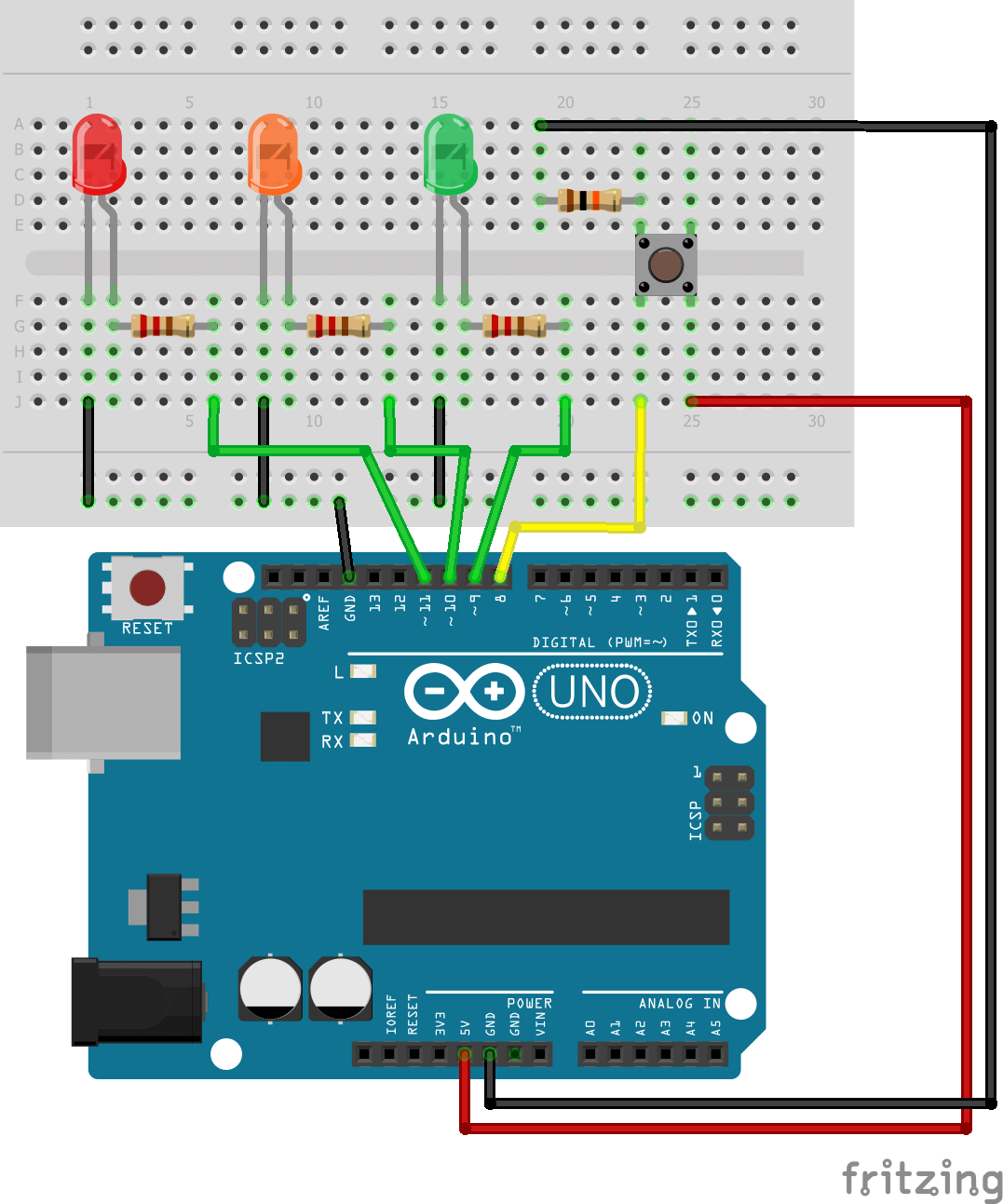
Control 3 LEDs with Arduino and one pushbutton • AranaCorp
Blinking an LED. Blinking an LED is an introductory Arduino project in which we control an LED using Arduino. LED blinking refers to the process of continuously turning an LED (Light Emitting Diode) and off in a repetitive pattern. It is a simple and common demonstration in electronics and microcontroller-based projects.
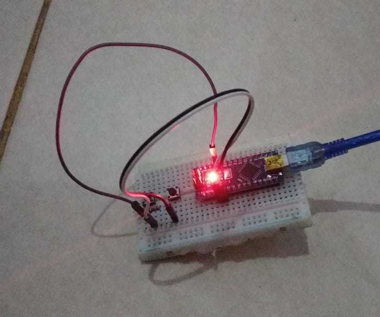
Control Builtin LED Using Push Button With Arduino Nano 3 Steps Instructables
Metasouls. Nov 2023 - Present 2 months. Amsterdam, North Holland, Netherlands. • Developing LinkedIn and Twitter B2B & B2C content strategy, creation, and marketing. • Tailoring content.
LED With Arduino 101 Hackster.io
The built-in RGB is located right next to the NINA-W102 Wi-Fi module on the MKR 1010 board. The RGB on board the MKR WiFi 1010 board. Controlling the RGB on the MKR WiFi 1010 is slightly different from any previous experiences you might have had with a similar component. First of all, we cannot access it directly, we need to use the.
Getting Started with Arduino LED Blinking
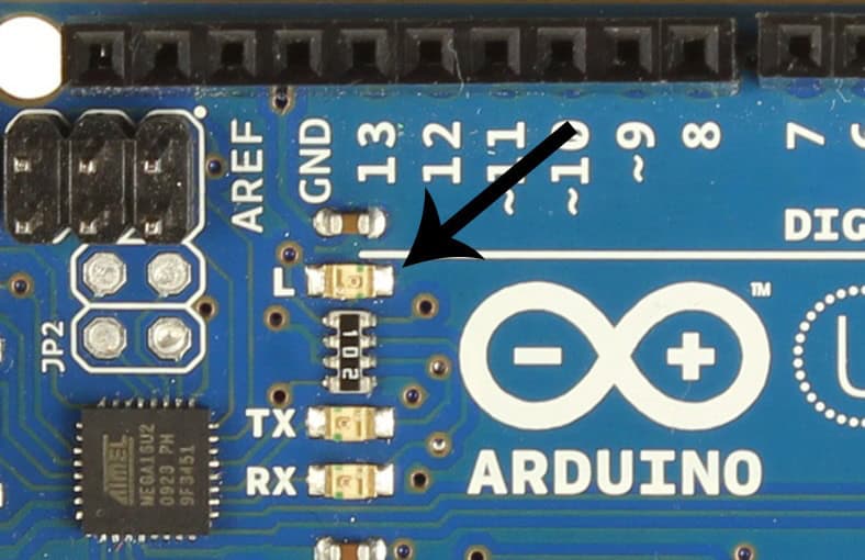
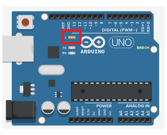
Arduino boards come with a little utility: the built-in LED. It is identified by the letter L next to it. On the Arduino Uno, it is near pin #13: On the Arduino MKR 1010 WiFi it is near the 5V output pin: This LED is connected to the digital I/O pin #13 in most boards. In some boards, like the Arduino MKR series, it's linked to the pin #6.

How to Blink LED with Arduino Nano Tutorial YouTube
// the setup function runs once when you press reset or power the board void setup () { // initialize digital pin LED_BUILTIN as an output. pinMode (13, OUTPUT); } 1 Like DrAzzy March 17, 2017, 3:40pm 2 LED_BUILTIN is the pin with the on-board LED (pin13 on most boards).
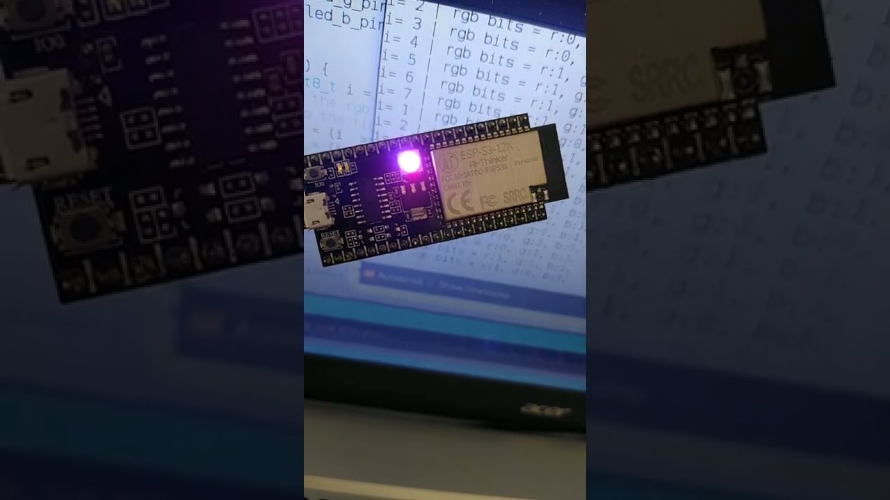
Blink builtin RGB LED ESP32S3 Arduino YouTube
LED 220 ohm resistor Circuit This example uses the built-in LED that most Arduino boards have. This LED is connected to a digital pin and its number may vary from board type to board type. To make your life easier, we have a constant that is specified in every board descriptor file.
Getting Started with the Arduino Controlling the LED (Part 1)
The brightness can be adjusted by making the LED blink. Actually operate the LED step by step to see how the brightness shifts. Connect the LED to pin 5 of Arduino, as shown below: Next, create the program as shown below and write it to Arduino. The LED should blink at one-second intervals. const int LED_PIN = 5;

Integrated LED in Arduino Arduino Project Hub
The LED blinking sketch is the first program that you should run to test whether your Arduino board is working and is configured correctly. An LED, which stands for Light-Emitting Diode, is a small electronic component that's a bit like a lightbulb, but is more efficient and requires a lower voltage to operate.
Arduino LED Complete Tutorial The Robotics BackEnd
If you want a retro feel, then you can inspiration in DIY GUY Chris's gorgeous LED matrix. This is a dot-matrix LED display with an overall resolution of 32×8. But that description alone doesn't do the project justice. Chris used tiny 0603 SMD LEDs, which allowed for very high "pixel" density and that results in better clarity than a.

BLINKING THE ONBOARD LED Arduino tutorial 1 YouTube
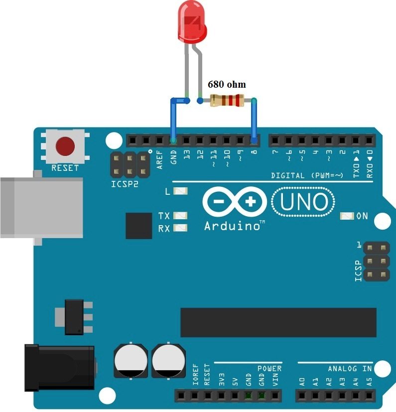
For this circuit we will need: Arduino board. LED (any color, I will use red). Breadboard. 220 Ohm resistor (more info on the value later on). Some male to female wires. Build the circuit Here is the circuit. How to build the circuit: First make sure that the Arduino is powered off (no USB cable plugged to anything).

The Arduino builtin LED
Learn step-by-step to program the built-in LED with the Arduino IDE. Download code and course material from https://arduino-tutorials.net/tutorial/blinking-l.

Arduino RGB LED Tutorial Starting Electronics
Aspiring architectural engineer with a background in architectural design, sustainability and circular design applications. TU Delft Graduate with specialization in facade engineering and climate design. Expertise in extreme environment architectural and facade design demonstrated by senior graduation project: "Building on Mars" in collaboration with Aerospace Engineering Faculty, TU Delft.
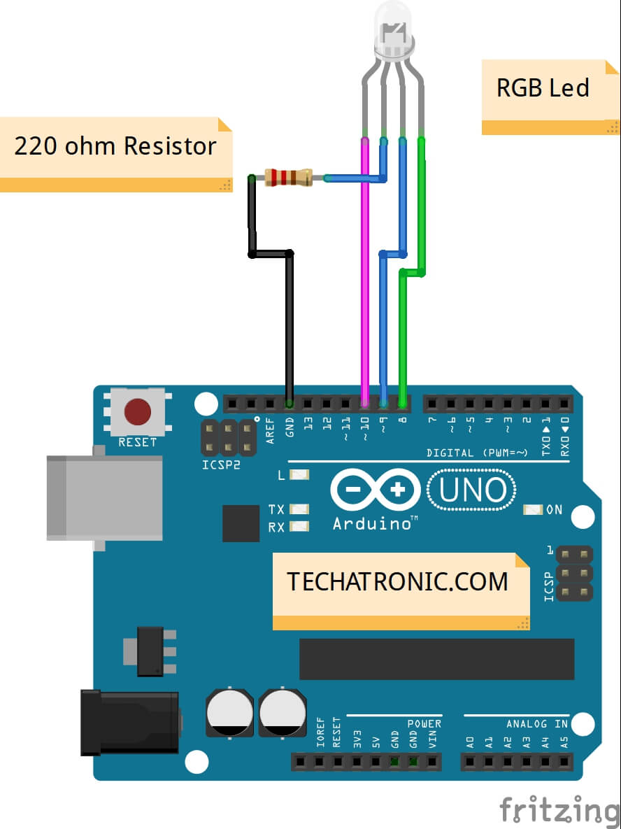
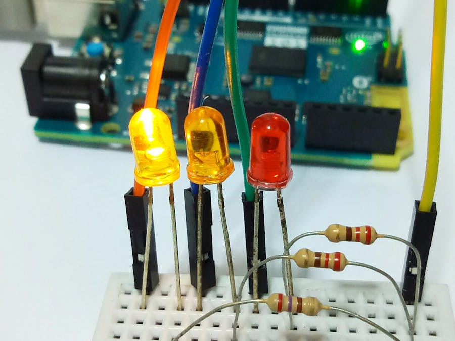
RGB Led with Arduino UNO Example TECHATRONIC
Arduino has a built-in LED on digital pin 13. Now we will control it using the push button. Let's make it! Ask Question Supplies 1. Arduino Nano 2. Female to female jumper cable (3 pcs) 3. Mini USB cable 4. 220 Ohm resistor 5. Breadboard Ask Question Step 1: Wiring Follow the wiring diagram as shown. 5 V --> one leg of push-button
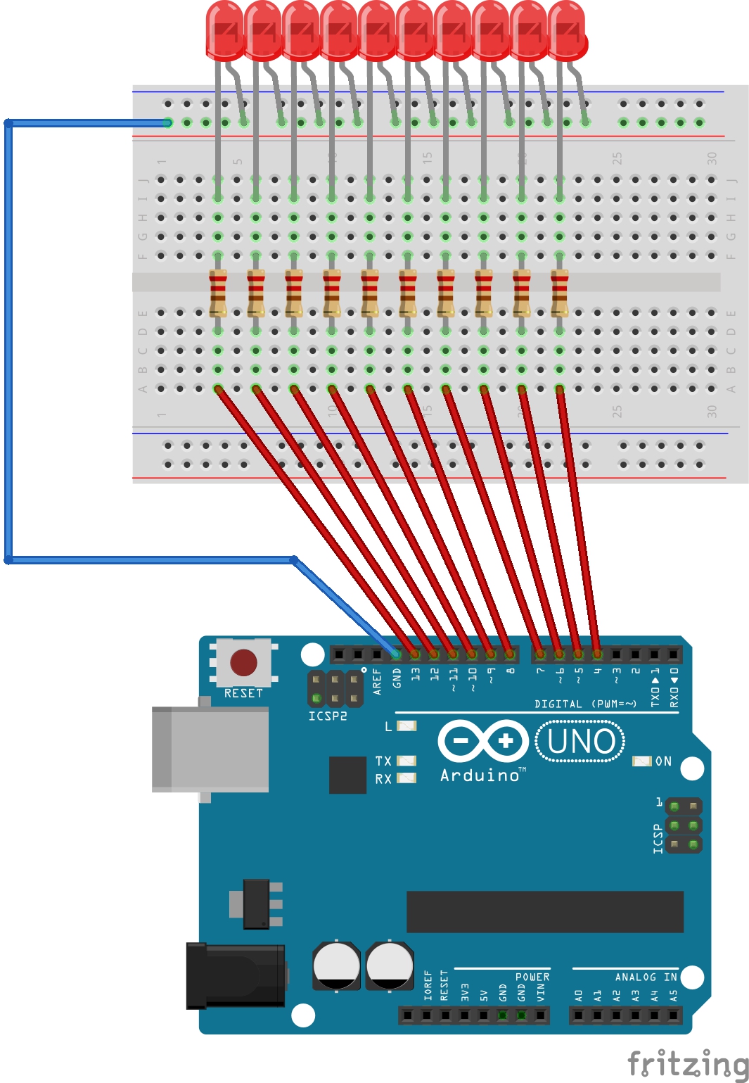
9 LED Patterns with Arduino Arduino Project Hub
How It Works After connecting the cathode (-) to GND: If connecting GND to the anode (+), LED is OFF. If connecting VCC to the anode (+), LED is ON. Besides, if generating a PWM signal to the anode (+), the brightness of LED is changed according to PWM value ( described in detail in this tutorial) ※ NOTE THAT:
LED blink Arduino Nano Tutorial eediary
#1 · Blinking Arduino's builtin LED Tutorial goals Blinking the onboard LED Working with the Arduino IDE Knowing how to upload a sketch to your Arduino Components needed 1× Arduino 1× USB cable 1× Computer Buy components $ 7.35 Arduino Uno (clone) with cable $ 35.89 5x Arduino Uno (clone) $ 14.54 Arduino Uno (clone)