4l60e Park Neutral Switch Wiring Diagram Wiring Diagram Schemas
The 4L60E transmission wiring diagram is a labyrinth of intricate connections that navigate electrons from point A to B in order to facilitate smooth gear shifts. Like a conductor leading an orchestra, it ensures harmonious synchronization between engine power and transmission performance. This diagram holds the key to unlocking the mysteries of this remarkable piece of automotive engineering.
4L60E Wiring Diagram Wiring Diagram
The external wiring harness for a 4L60E will need to be spliced into the main wiring harness. It's not that difficult to do, just make sure that you solder it in and cover it with heat shrink. The 4L60E has been produced since the early 90's. While retaining the same basic gearing, it has undergone some design changes from time to time.
31 4l60e Transmission Wiring Diagram Wiring Diagram Database
Below is the diagram for the 4l60e transmission external wiring harness. Image Courtesy: CPT 4L60E From the diagram above, you can see the external wiring harness for the 4160e transmission comprises various parts. These include: 1. Shift solenoids The external wiring harness of the 4l60e boasts two shift solenoids, including upshift and downshift.

Bestly 4l60e Transmission Neutral Safety Switch Wiring Diagram
Wiring & Diagrams Affiliate Disclosure CPT 4l60e participates in the Amazon Associates program, an affiliate advertising program designed to provide a means for sites to earn advertising fees by advertising and linking to Amazon.com, as well as other participating programs to help fund and maintain the website.

4l60e Neutral Safety Switch Wiring Diagram Free Wiring Diagram
But did you check eBay? Check Out 4l60e on eBay. Fast and Free Shipping on many items you love on eBay.
4L60E Transmission Wiring Diagram Wiring Diagram
Here are a few specs for the 4L60E: The length comes in at 21.9″. Dry weight is 146 lbs. Cast Aluminum case. 360 lb ft (488 N.m) maximum torque. 8.4 qt. (9.64-inch torque-converter) or 11.4 qt.

Best 4l60e Transmission Wiring Diagram MegaShift 4L60E New 4L60e Transmission, Chevy
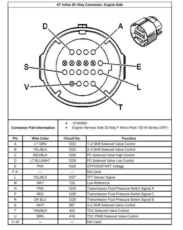
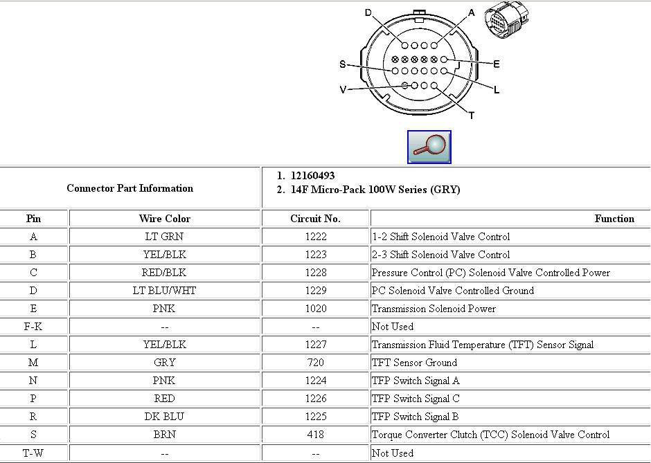
Transmission harness plug pin identification 2007 and up Gear Ratios and clutch/solenoid charts Pressure testing transmission Gauge port location, use 0-400 psi gauge Reverse: 64-324 psi (min/max) Park, neutral, drive ranges 55-189 (min/max)
4l60e tcc wiring diagram
This system works with 4L60E, 4L65E, and 4L70E automatic transmissions from 2008 and. It is recommended that you use the Baumann wiring harness with this system. 3 CONTENTS Connecting the Essentials Page 4 Setting up the Quick 4 Page 8 Notes on Installation Page 10 Transmission Diagrams Page 12 Optional Features Page 13 Manual Shift.
4l60e transfer case wiring diagram
A few different types of Transmission Output Shaft Speed (TOSS) sensors are used in the GM 4L80E / 4L60E Series. Two (2) different adapter wires are shown here. In both cases, one side of the adapter wires plugs into the TOSS sensor; the other plugs into the COMPUSHIFT II wiring harness. The connector with the orange gasket fits early-4L60E.
4L60E Transmission Wiring Diagram Wiring Diagram
GM 4L60/80E Transmission Harness - Complete terminated harness with j4 connector to operate GM electronic transmissions. For 2009+ GM 4L60/80E Transmission use Holley EFI Part Number 558-455.
4l60e Exploded Diagram General Wiring Diagram
¡Precios increíbles y alta calidad aquí en Temu. Envío gratuito en todos los pedidos. ¡Solo hoy, disfruta de todas las categorías hasta un 90% de descuento en tu compra.
4L60E Transmission Wiring Diagram Wiring Diagram
4L60E, 4L65E, and 4L70E Transmissions.. the Baumann wiring harness with this system. 2. CONTENTS Connecting the Essentials Page 4 Setting up the Quick 4 Page 9 Notes on Installation Page 11 Transmission Diagrams Page 13 Optional Features Page 14 Manual Shift Connections Page 19 Built-In Display / Remote Display Page 23

New Of 4l60e Transmission Shift Solenoid Wiring Diagram What Turns Throughout 4L60e Electrical
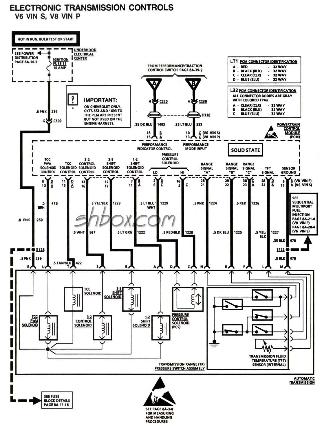
The 4L60E is controlled through 14 pins. These are: The wiring inside the 4L60E transmission looks like this: The corresponding AMPseal connections for the control/sense functions are: In addition there are: On the GPIO, the connections are: CANH: Ampseal connector pin 13, CANL: Ampseal connector pin 16. On MS-II controllers, the CAN paths are:
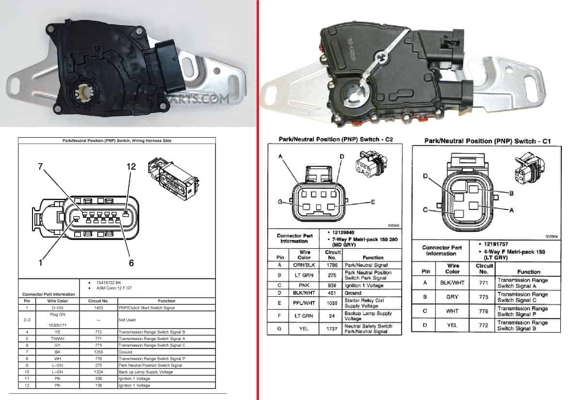
4l60e Neutral Safety Switch Diagram CPT 4l60e
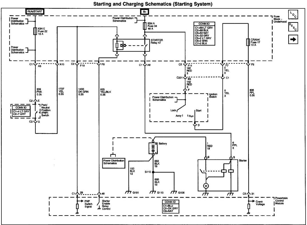
In the wiring diagram for the 4l60e neutral safety switch, you will find various connections and terminals. One terminal is connected to the ignition switch, which sends a voltage signal to the neutral safety switch. Another terminal is connected to the ECM or PCM, allowing the switch to send a signal to the control module.
4l60e Neurtal Wiring Diagram
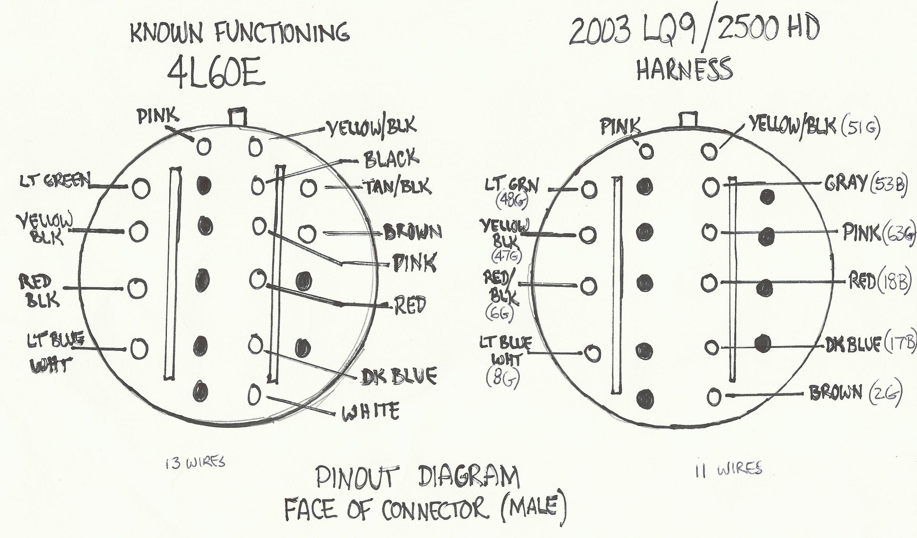
COMPUSHIFT II Manual / Specifications & Pinouts / Connector Pinouts Pinouts for GM 4L60E and 4L80E TRANS 1 Connector Note: This is the view into the receptacle on controller, not the plug. ENGINE Connector Note: This is the view into the receptacle on controller, not the plug. OPTIONS Connector
Gm 4l60e Transmission Wiring Diagram Unity Wiring
4l60e Valve Body Diagram 4l60e Valve Body Identification Guide 4l60e Mechanical Components Diagram Previous Article 4l60e Transmission Cooler Line Flow Next Article 4l60e Transmission Fluid and Filter Change Review internal and external 4l60e wire harness wiring diagrams for your swap or repair needs.