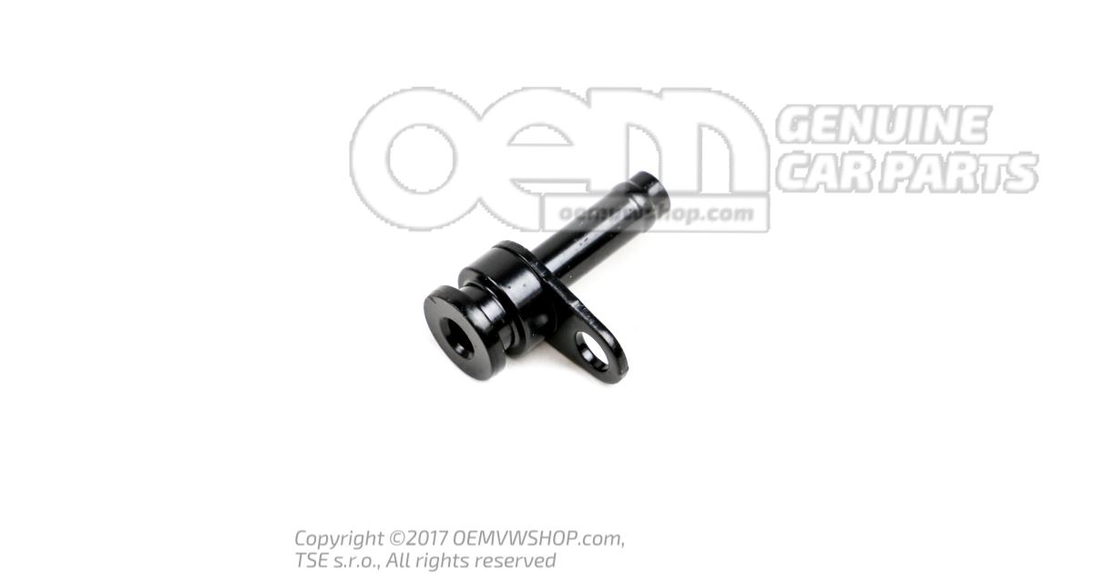
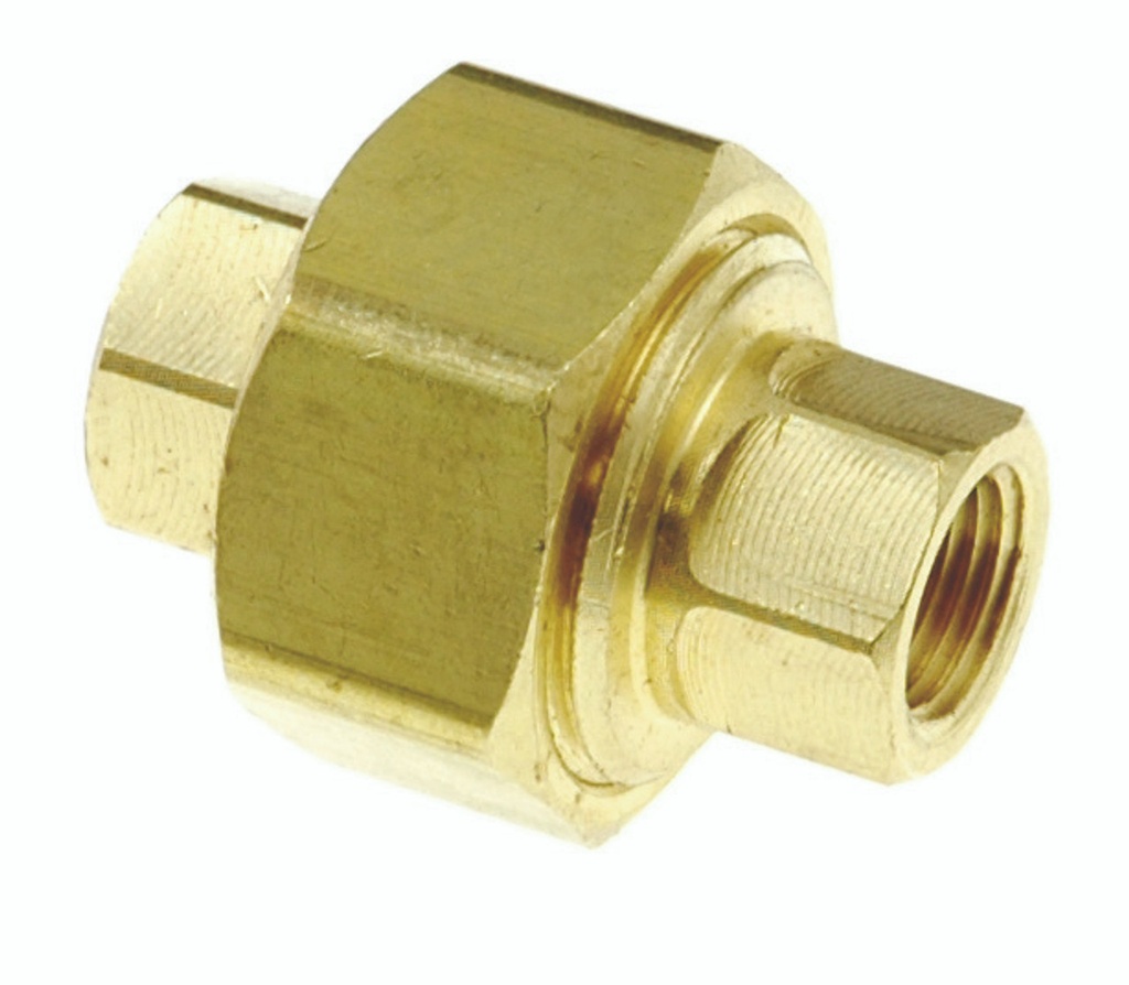
Pipe union 059121065DS
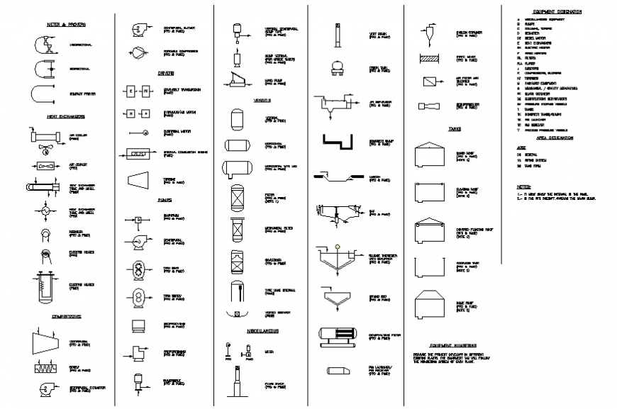
Piping and Instrument Diagram Standard Symbols Detailed Documentation provides a standard set of shapes & symbols for documenting P&ID and PFD, including standard shapes of instrument, valves, pump, heating exchanges, mixers, crushers, vessels, compressors, filters, motors and connecting shapes.

2 inch Brass Pipe Union at Rs 55/piece in Delhi ID 26744535955
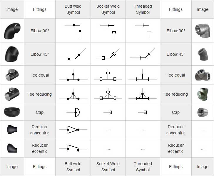
There may be multiple symbols for one fitting or part depending on the fashion it is to be installed (Butt weld, Socket Weld, Threaded.) Below is a breakdown of almost every type of fitting and connection. Coordination System Symbols for Isometrics Note: Symbols are shown in black lines.
Plumbing Equipment Designation Symbols Drawing In Dwg File Symbol SexiezPicz Web Porn
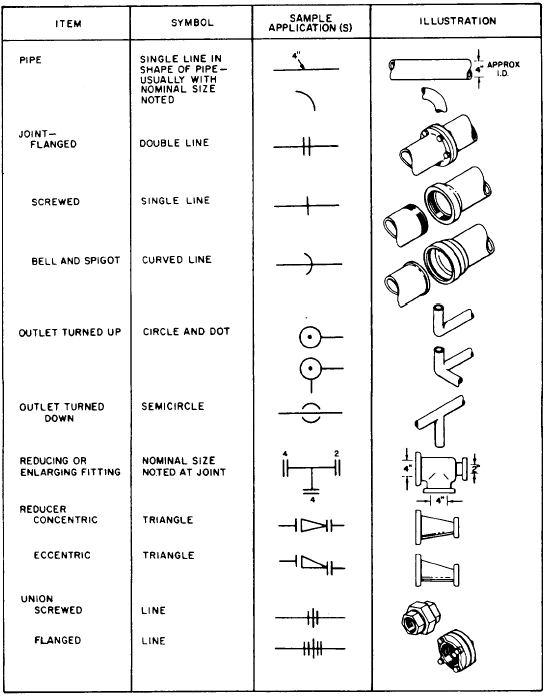
SYMBOLS FOR PIPE FITTINGS --------------------
Flanged Screwed
Bell And
Spigot
Welded
Soldered
Bushing
6
4
Cap
Cross
(Reducing)
6
2
4
6
6
2
4
6

Schematic Symbols Archives Circuit Diagrams
WHAT IS P&ID? P&ID is the acronym for "Piping and instrumentation diagram", i.e. a very detailed diagram showing the processes happening within a plant, the involved equipment, and their interconnections. A set of standardized P&ID symbols is used by process engineers to draft such diagrams.

Piping Diagram Symbols Valves
Know and identify pipe fitting symbols on your Piping Isometrics (flanges, reductions, caps, spool pieces, unions…) Know and identify the Piping Isometric symbols of safety devices that are used to safely isolate, vent & drain process equipment for ease of maintenance (spectacle and spade blinds, double block, and bleed valves…)
Din Wiring Diagram Symbols beeter thing then money is wiring
Isometrics Symbols. Note.. Symbols are shown in black lines. Lighter lines show connected pipe, and are not parts of the symbols. safety.

Pin on Interior Design
-- SYMBOLS FOR PIPE FITTINGS Bell And Flanged Screwed Spigot Welded Soldered Valve - Gate Motor Operated Valve - Globe Valve - Globe Motor Operated Valve - Angle Hose Angle Valve - Hose Gate Valve - Hose Globe Valve - Lockshield Valve - Quick Opening Valve - Saftey Sleeve
Discover 70+ pipe drawing symbols best nhadathoangha.vn
Union: This symbol represents a fitting used to connect two pipes together that can be easily disconnected for maintenance. It is important to note that these symbols can be combined to create more complex piping systems.

2 Inch ( Dia ) 20mm PPR Pipe Union at Rs 70/piece in Secunderabad ID 2851325796873
Union (flanged) Strainer (specify type) Pipe anchor: PA: Pipe guide: Expansion joint: EJ: Flexible connector: FC: Tee: Concentric reducer: Eccentric reducer: TABLE 1-5. Symbols: Description:. Pipe hanger: This symbol is a diagonal stroke imposed on the pipe that it supports. Alarm check valve: Specify size, direction of flow. Dry pipe valve:
Pipe Union DuraPro Health
Symbols for single line piping arrangement drawings - butt weld,. Union Swage concentric. Union Swage concentric: Swage eccentric: Top view: Note.. Symbols are shown in black lines. Lighter lines show connected pipe, and are not parts of the symbols. safety. documents. materials. societies. pipes. flanges. fittings. valves. bolts. gaskets.

81359442 Symbols for Pipe Fittings
Use of plumbing symbols: Size mentioning. Time tracking by mentioning time on symbols. Adding various equipment on a map. Adding extra details.

Piping Coordination System Mechanical symbols for Isometric drawings Mechanical symbols
P&ID Symbols for Piping. Clamped Flange Coupling: Coupling: End Caps 01: End Caps 02: Flange: Flanges: Reducers: Removable Spool: Union [google-square-ad] Click to print (Opens in new window) Click to email a link to a friend (Opens in new window) Click to share on Facebook (Opens in new window) Click to share on Twitter (Opens in new window.
Fitting symbols
0 August 18, 2023 Piping and Connecting Shapes Piping and Instrument Diagram Standard Symbols Detailed Documentation provides a standard set of shapes & symbols for documenting P&ID and PFD, including standard shapes of Piping and Connecting Shapes. Continue Reading

Symbols Used for PIPE JOINTS & FITTINGS in Engineering Drawing//Pipe Joint Symbols//ITI 1st Year
Various symbols are used to indicate piping components, instrumentation, equipments in engineering drawings such as Piping and Instrumentation Diagram (P&ID), Isometric Drawings, Plot Plan, Equipment Layout, Welding drawings etc. Checkout list of such symbols given below. PID Symbols Instrumentation Crushers Mixers Motors Dryers Valves Centrifuges

Terpopuler 33+ Elbow Pipe Symbol
In this video we explain about the important symbols that are used for pipe joint and fittings in engineering drawing. This topic is taken from ITI first yea.

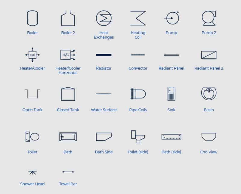
Plumbing and Piping Plan Symbols
P&ID is an abbreviation meaning ' Piping and Instrumentation Diagram '. Piping and Instrumentation Diagrams are graphical representations of a process system. These are fundamental to every standardized engineering project. These two-dimensional diagrams function as a blueprint for the engineering system's design.