Lab6 Designing NAND, NOR, and XOR gates for use to design fulladders
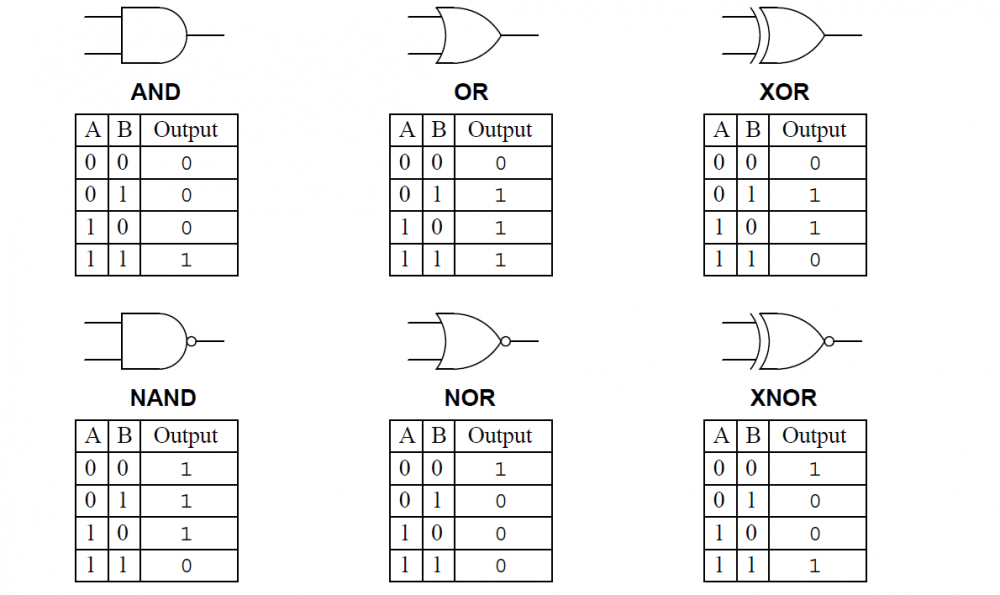
The XOR gate also has the same number of inputs and output. This logic gate works like this-0 + 0 => 0 0 + 1 => 1 1 + 0 => 1 1 + 1 => 0. Here, the input needs to be exclusive. As you can see in the above flowchart, the output is false where both the inputs are true. NOR. The NOR gate is a NOT-OR gate which is a bit similar to the NOT gate.

NAND, NOR & XOR Logic Gates Video & Lesson Transcript
What is Boolean Algebra? The rules I mentioned above are described by a field of Mathematics called Boolean Algebra. In his 1854 book, British Mathematician George Boole proposed a systematic set of rules for manipulation of Truth Values. These rules gave a mathematical foundation for dealing with logical propositions.
x xor DriverLayer Search Engine
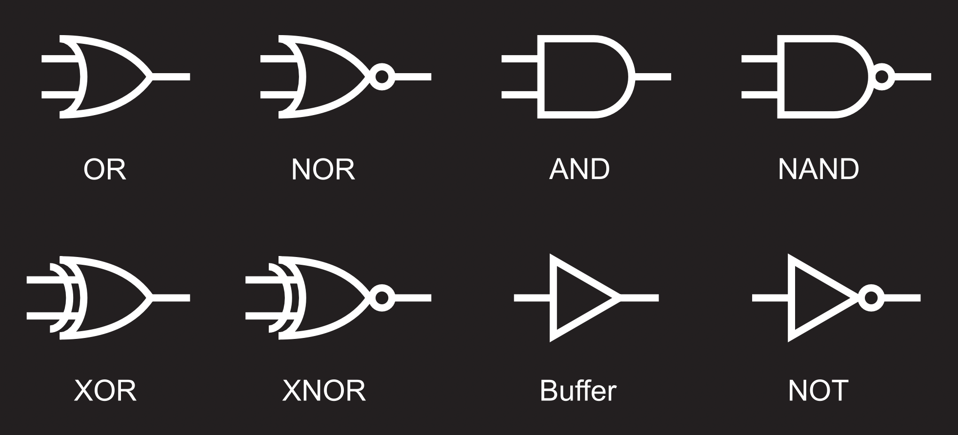
NOR; NAND; XOR; XNOR; Basic Logic Gates AND Gate. An AND gate has a single output and two or more inputs. When all of the inputs are 1, the output of this gate is 1. The AND gate's Boolean logic is Y=A.B if there are two inputs A and B. An AND gate's symbol and truth table are as follows: Input.

Logic Gates AND, OR, NOT, NOR, NAND, XOR, XNOR Gates Truth Table
The ^ operator computes the logical exclusive OR, also known as the logical XOR, of its operands. The result of x ^ y is true if x evaluates to true and y evaluates to false, or x evaluates to false and y evaluates to true. Otherwise, the result is false.
PPT XOR, XNOR, & Binary Adders PowerPoint Presentation ID4751540
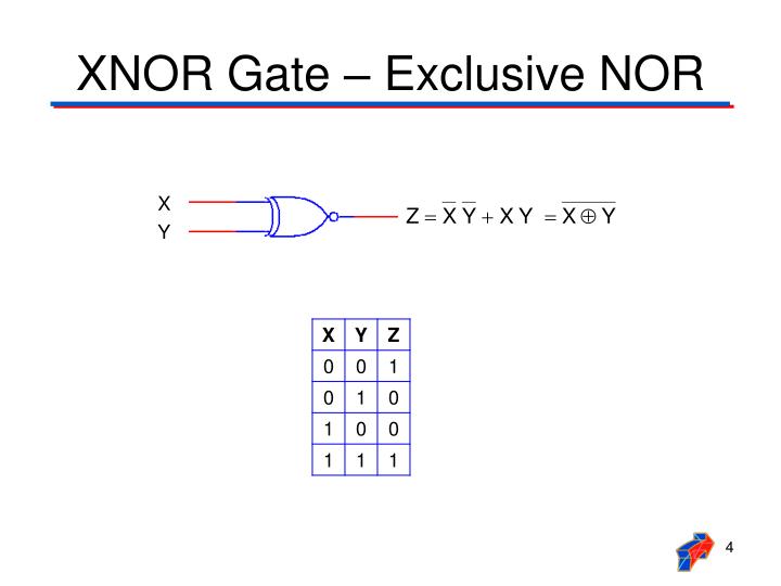
1. The XNOR gate (sometimes ENOR, EXNOR, NXOR, XAND and pronounced as Exclusive NOR) is a digital logic gate whose function is the logical complement of the Exclusive OR ( XOR) gate. [1] It is equivalent to the logical connective ( ) from mathematical logic, also known as the material biconditional. The two-input version implements logical.

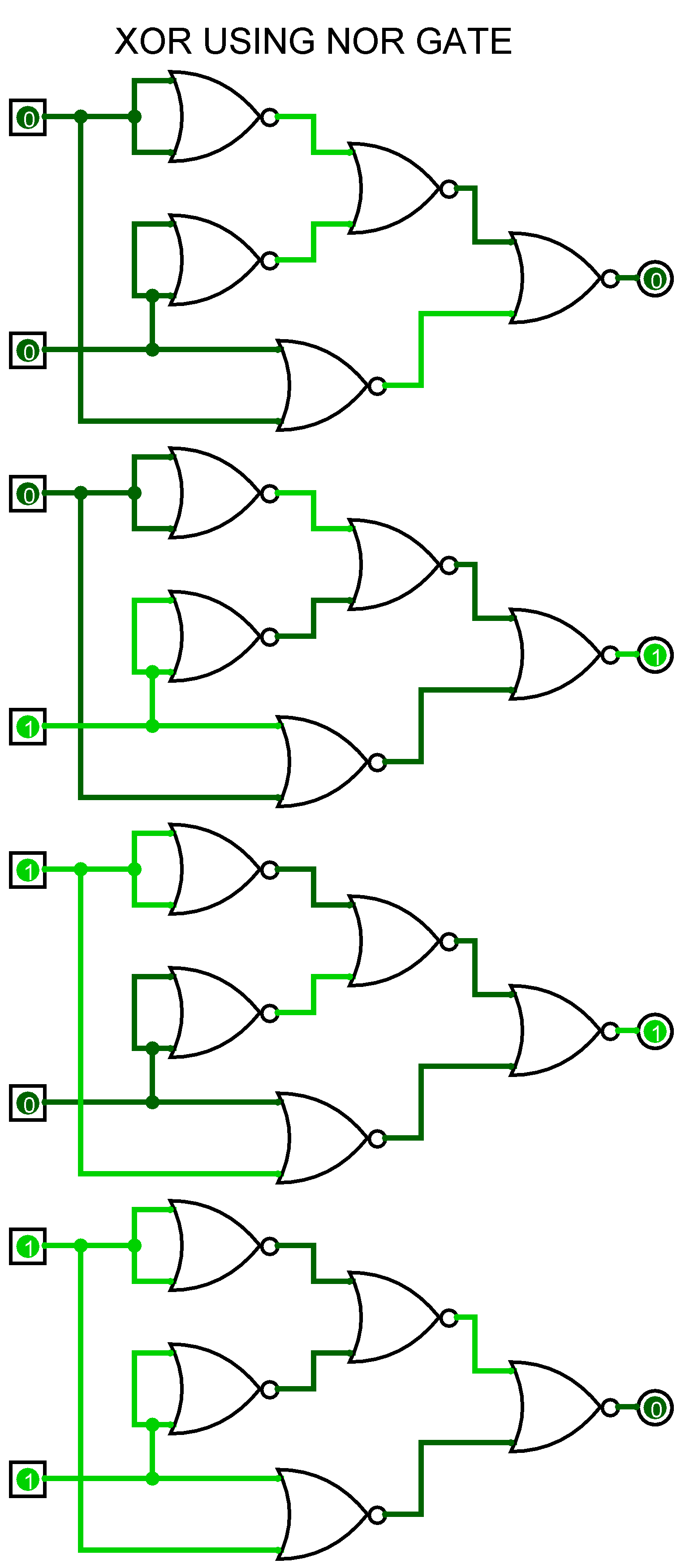
CircuitVerse XOR using NOR
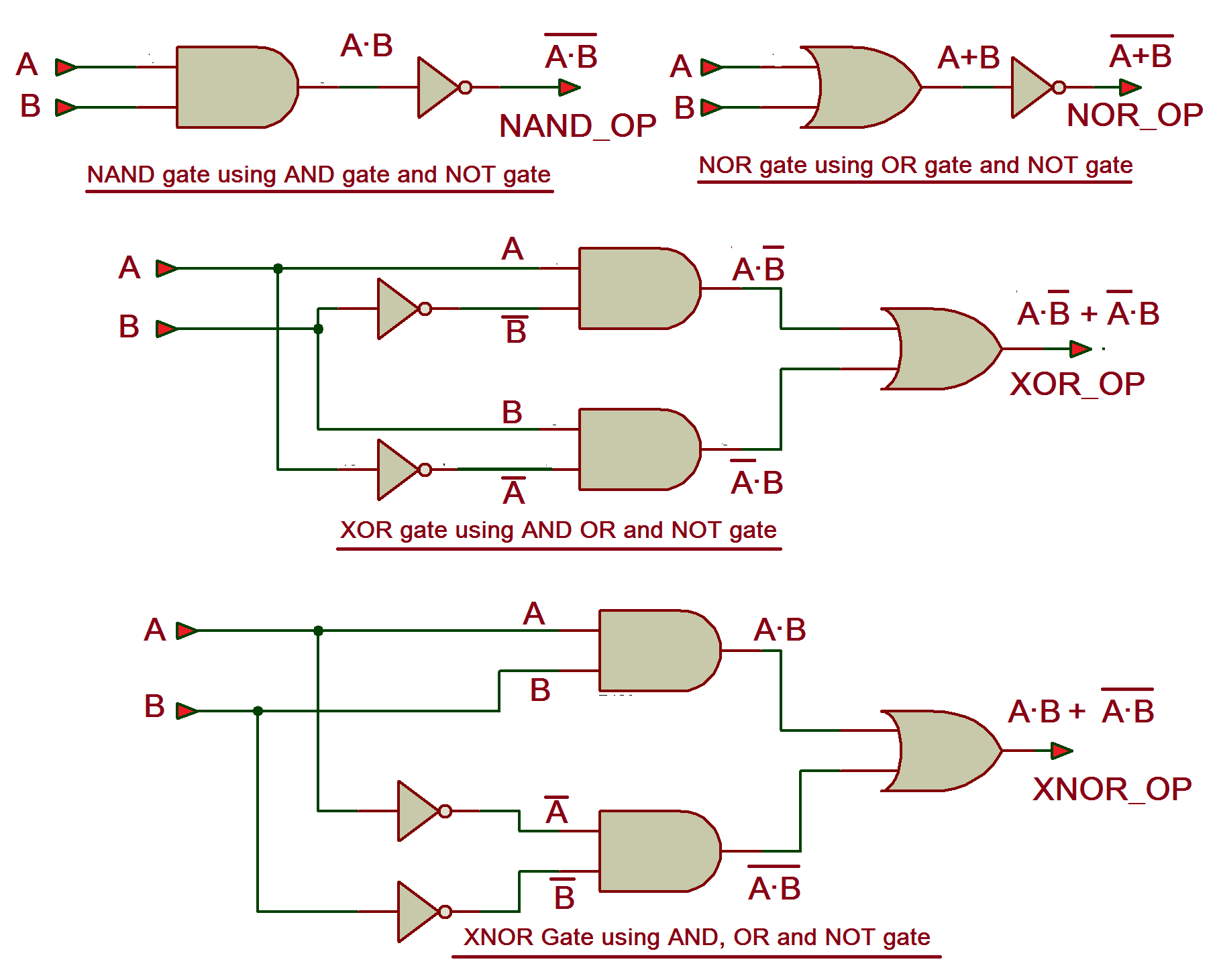
The NOR gate is essentially an OR gate whose output is then fed into a NOT gate. Therefore, it is true only in the case where both inputs are zeroes (the only case that would have made an OR gate output a '0'). The XOR gate is true when the inputs are opposite of each other, but false when they are equal. For example, the two inputs '1' and '0.

CircuitVerse NOR,XOR,XNOR using NAND
A logic gate is an electronic circuit that operates on one or more digital signals to produce an output signal. A logic gate performs a logical operation such as AND, OR, NOT, etc. on one more logic input (1 or 0) and produces a single logic output (1 or 0). Logic gates process signals which represent " true " or " false ".
Truth Table And Or Not Xor Xnor Gates In Hindi
'NOR' - an 'OR' gate combined with a 'NOT' gate 'XOR' (or 'eXclusive OR') - a variation on the 'OR' gate, if the two inputs to an 'OR' are both 'high' then their.

CircuitVerse NOR to XOR
There are seven basic logic gates: AND, OR, XOR, NOT, NAND, NOR and XNOR. The AND gate is named so because, if 0 is false and 1 is true, the gate acts in the same way as the logical "and" operator. The following illustration and table show the circuit symbol and logic combinations for an AND gate.
To Study and Verify the Truth Table of Logic Gates. AHIRLABS
The XNOR (exclusive NOR) gate is an essential element in the family of universal gates, alongside AND, OR, NOT, NAND, NOR, and XOR. Working Principle of XNOR Gates. An XNOR gate operates with binary inputs and delivers outputs based on a specific logic. The term 'exclusive' infers that the gate delivers a high output (1) when an odd number.
How Logic Gates Work OR, AND, XOR, NOR, NAND, XNOR, and NOT
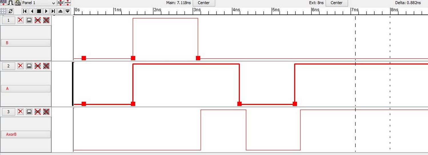
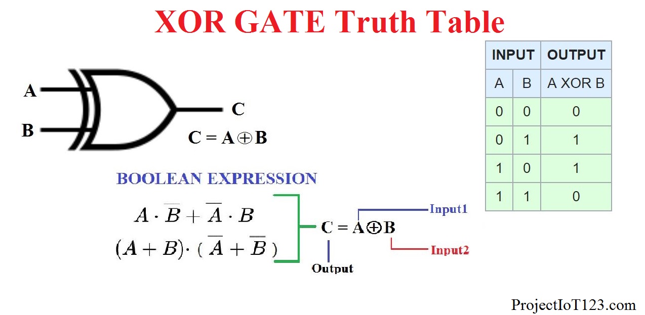
XOR gate (sometimes EOR, or EXOR and pronounced as Exclusive OR) is a digital logic gate that gives a true (1 or HIGH) output when the number of true inputs is odd. An XOR gate implements an exclusive or from mathematical logic; that is, a true output results if one, and only one, of the inputs to the gate is true.If both inputs are false (0/LOW) or both are true, a false output results.

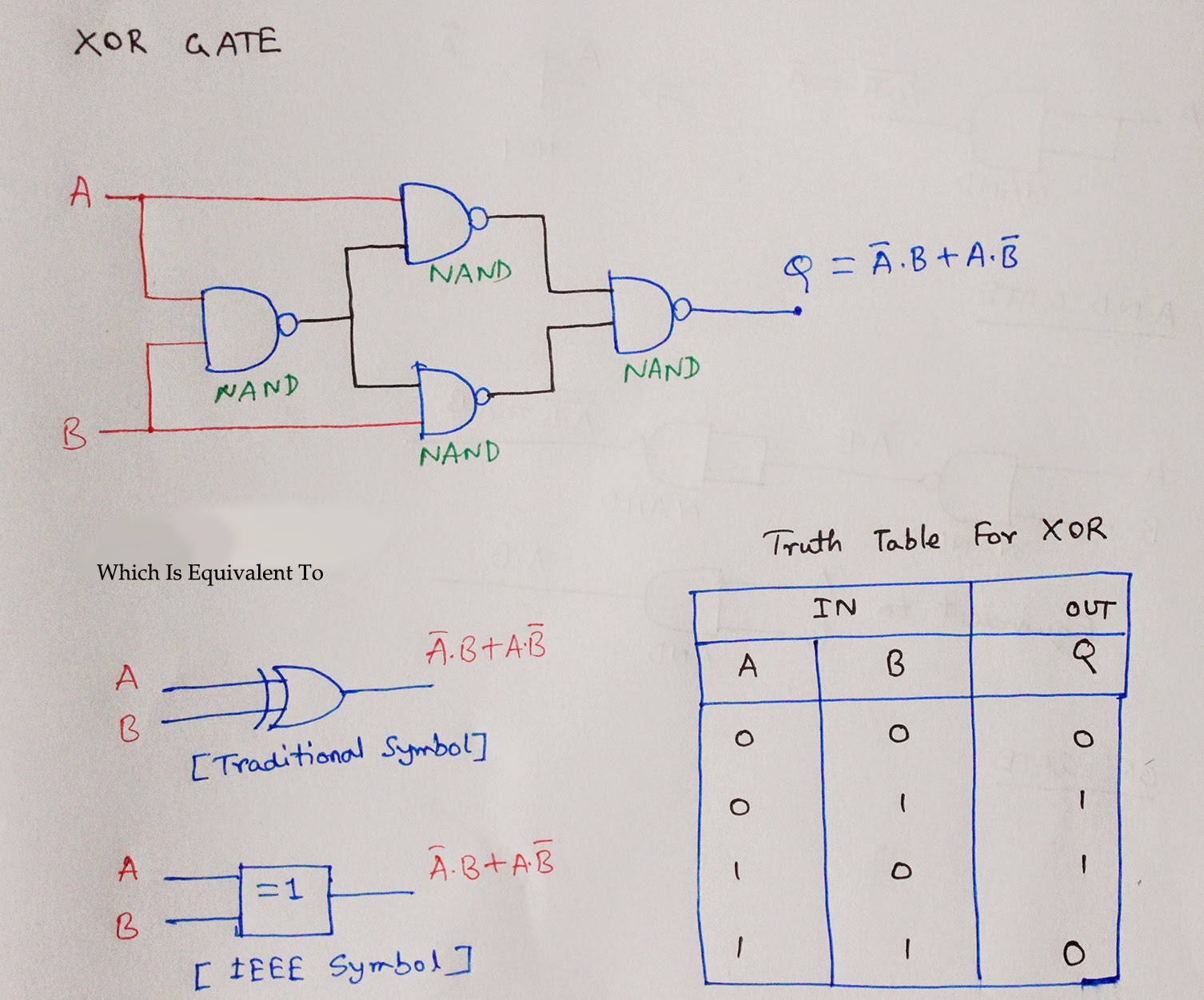
How to implement XOR gate 1) Using NAND only, 2) Using NOR gates only
Introduction to Logic Gates Logic gates are the basic building blocks of any digital system. They are used to create digital circuits and perform logical operations on binary inputs. The main types of logic gates include AND, OR, NAND, NOR, XOR, and XNOR.
Circuit Diagram Of Xnor Gate Using Nand Wiring Diagram
NAND gate NOR gate XOR gate and XNOR gate Among these logic gates, some are universal while others are basic. The term universal gate is derived from the idea that operations that can be performed with the basic logic gates such as AND, OR, and NOT can be performed with just a single logic gate.

Logic Gates in detail NOT, OR, AND, NOR, NAND, XOR, XNOR Universal
NAND XNOR NOT Logic Gates in Computer Code Wrapping up Logic gate: a cool term, but what does it mean? This article will introduce the concept of a logic gate as well as describe how each specific logic gate (OR, AND, XOR, NOR, NAND, XNOR, and NOT) works. What Is a Logic Gate? First, it's important to realize that logic gates take many forms.
Brief Tutorial Of Xor And Xnor Logic Gates
XOR Gate. An XOR is known as exclusive-OR gate and is almost similar to an OR gate with the only difference that when both the inputs are 1 or True, the output is 0 or False, unlike an OR gate. Hence the truth table for the XOR gate is shown as follows and the symbol for it can be seen in figure below along with its truth table.
Exclusive OR/ Exclusive NOR Tables for XOR/XNOR
Logic Gate Simulator A free, simple, online logic gate simulator. Investigate the behaviour of AND, OR, NOT, NAND, NOR and XOR gates. Select gates from the dropdown list and click "add node" to add more gates. Drag from the hollow circles to the solid circles to make connections. Right click connections to delete them.