USB Wiring Code Wiring Diagram
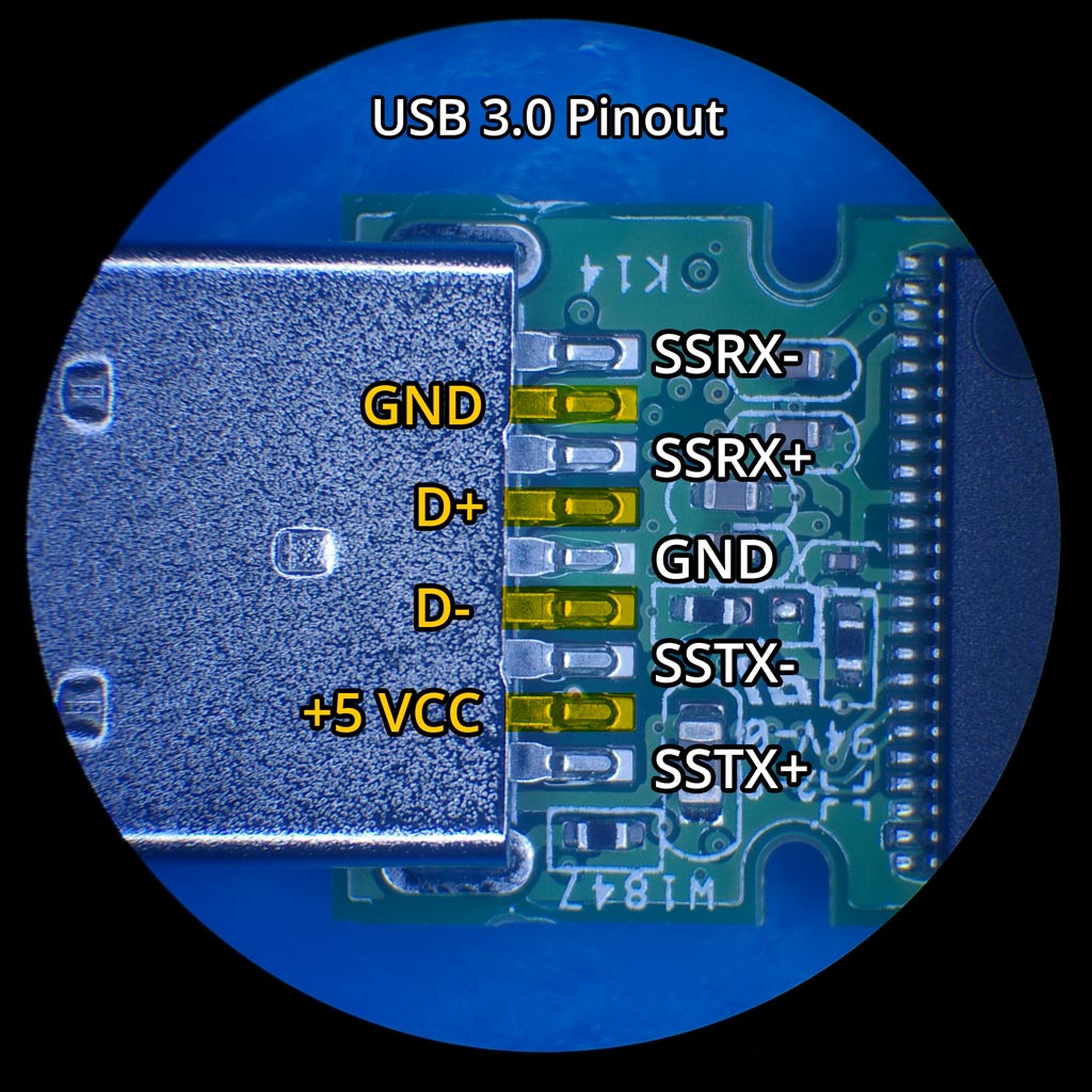
USB Type A Pinout. The Type A connector has four pins in its older generations and nine pins in the current 3.0 generation. Here's a chart showing the pins on the current Type A connector: Looking at the Type A connector on a cable, all generations contain pins numbered 4-1. These pins are descending from left to right on the bottom.
Свързване на USB конектор. Схема за запояване
What is a USB pinout A USB pinout refers to the arrangement of pins or connectors on a USB cable or port. It specifies the signaling and electrical characteristics of each pin to ensure proper communication and power delivery between devices.
micro usb wiring colors Wiring Diagram
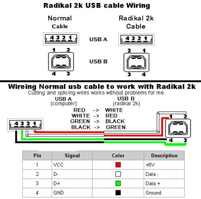
The USB A pinout consists of four pins, each with a unique function: VCC (Pin 1): This is the power supply pin, providing a +5V voltage to the connected device. D- (Pin 2): This is the Data Minus pin, responsible for carrying data. D+ (Pin 3): This is the Data Plus pin, working together with Pin 2 for data transmission.
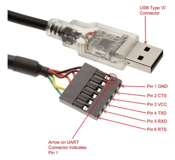
FTDI Cable Pinout, Applications and How to use it ( Windows + Linux )
USB-A. USB-A, or USB Type A, is the original flat and rectangular connector that no one could ever figure out how to plug in correctly the first time. These cables always have USB-A on one end with a different port type on the other, and can be used for device charging and data transfer. USB-A is still widely used and can be found on devices.

USB cable and pinout Knowledge Pinterest Tech and Arduino
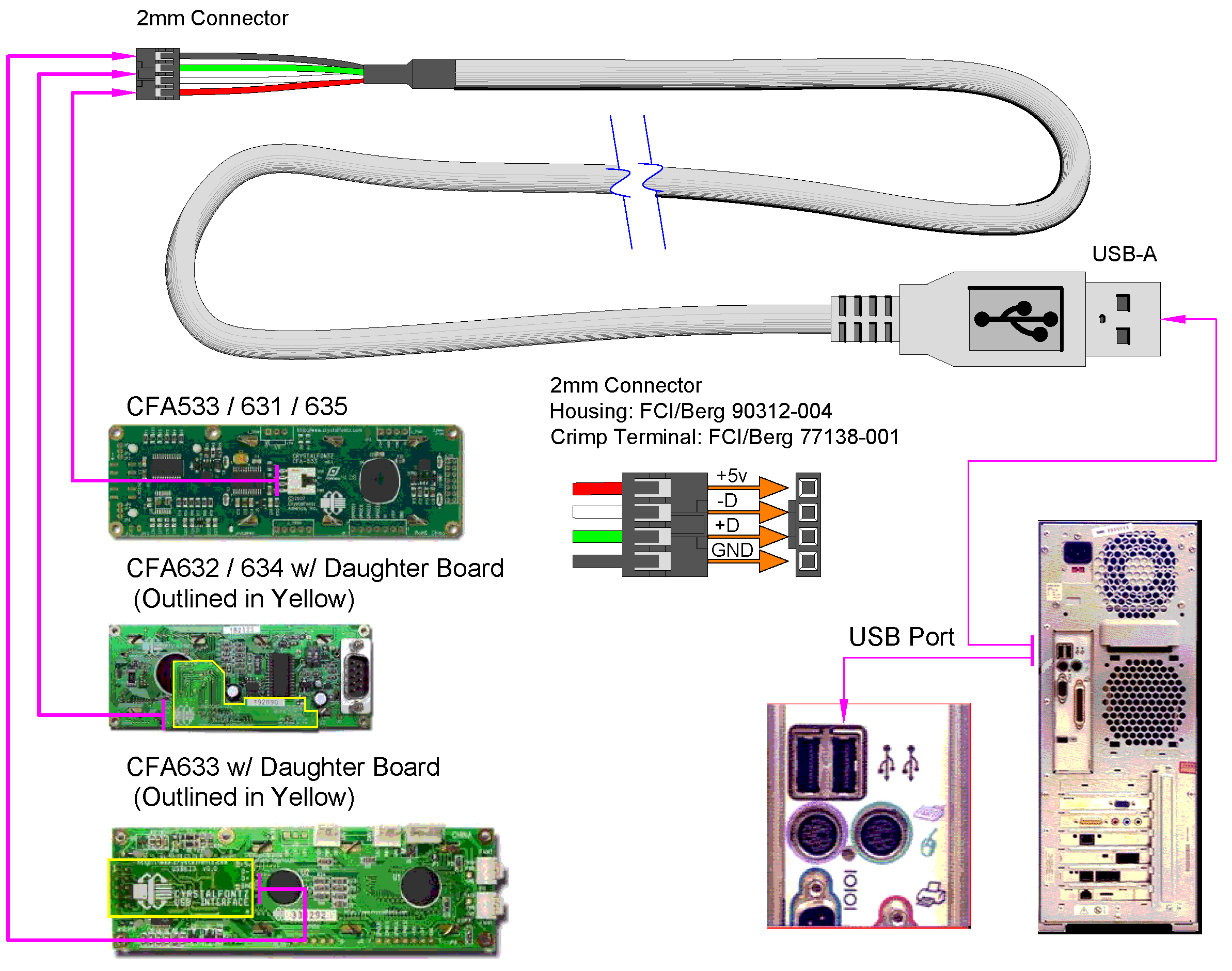
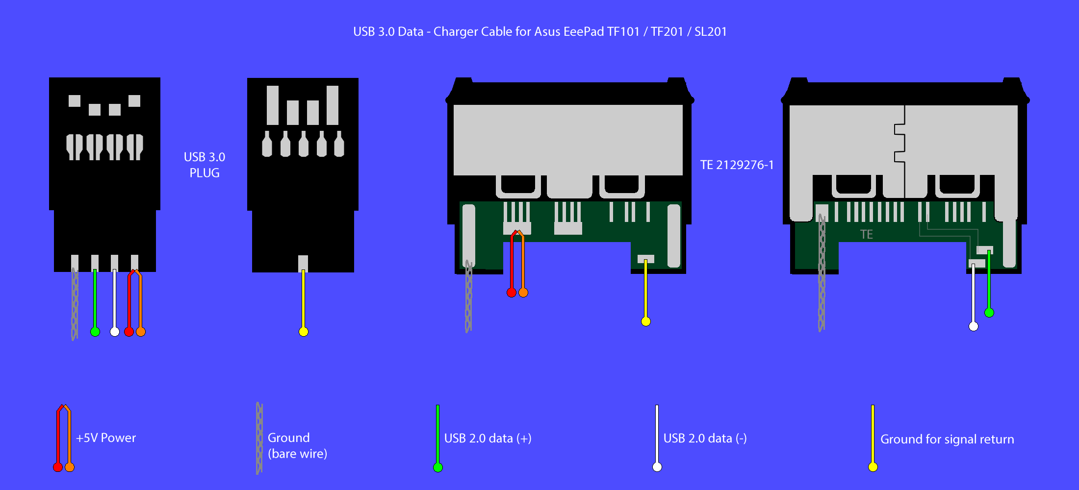
USB 2.0 cable wiring pinout Pinouts > Serial interfaces cables and converters scheme 4 pin USB A receptacle connector Very simple. Maximum length of cable is about 5 m for AWG20 and 0.8 m for AWG28 cable. USB D+ and D- are twisted in cable. Outer shell is made of copper braid and aluminum shield. Colors do not mean anything in the wiring scheme.
Usb Pinout Wiring Diagram Wiring & Engine Diagram
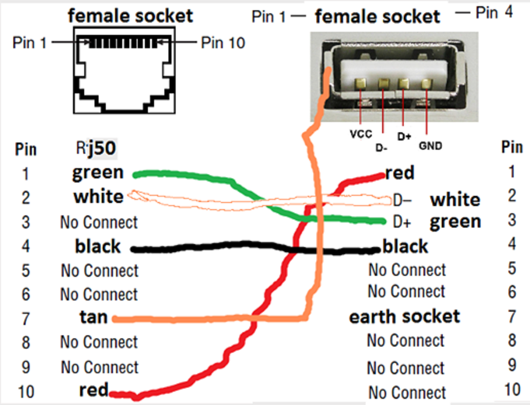
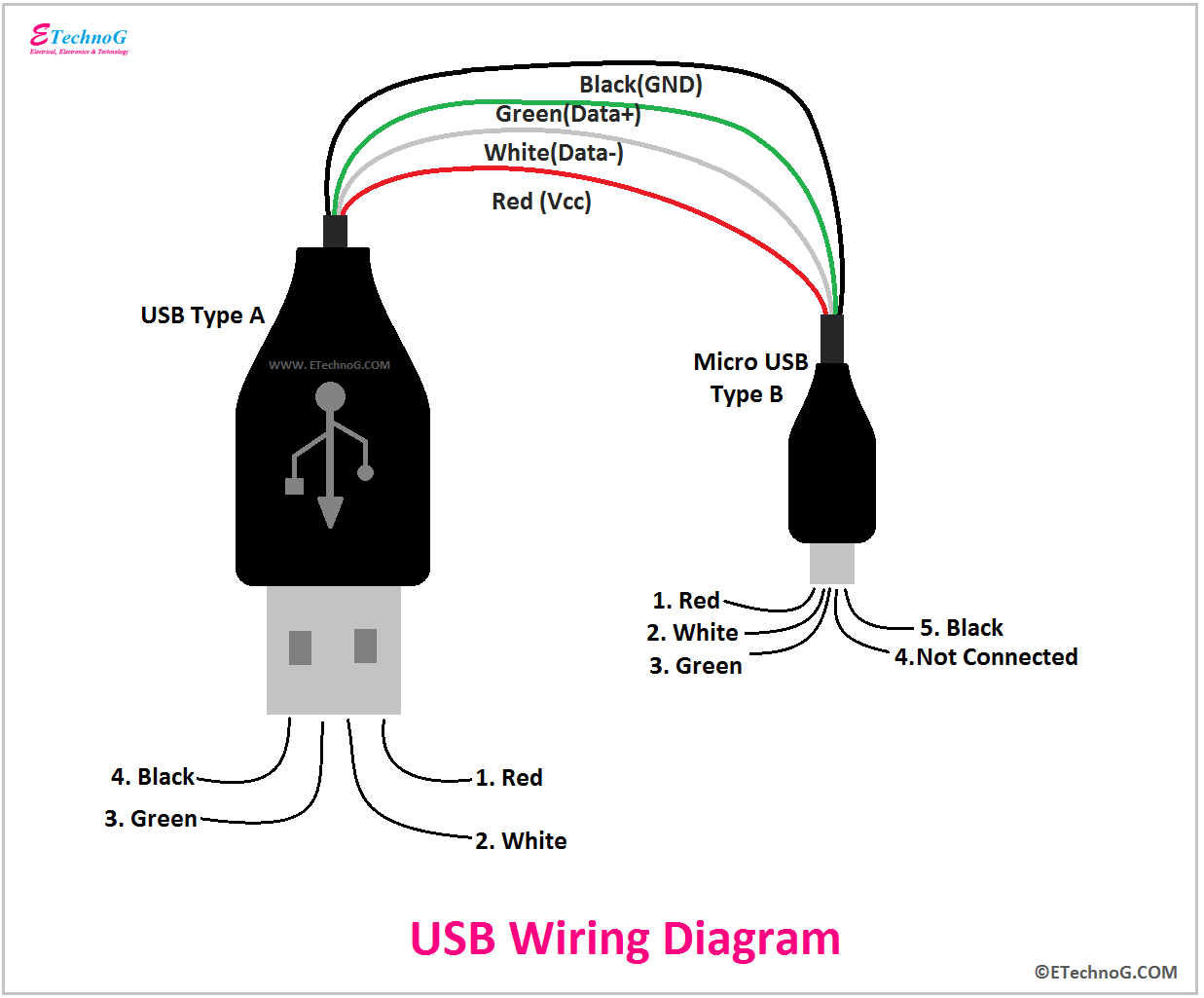
There are four wires inside a cable: red, white, black, and green. This is the most common type of combination. Each of these wires has its own purpose. The >white wire is the positive Data wire. (D+). The green wire is the negative. (D-). Both of these wires are involved in data transfer.
USB Wiring Diagram, Connection, PinOut, Terminals ETechnoG
USB is supposedly universal, but there are so many different types of USB cables and connections. Why is this? As it turns out, they each serve different functions, mainly to preserve compatibility and support new devices. Here are the six most common types of USB cables and connectors:
USB Flash Device Connector Pinout
Universal Serial Bus (USB) is an interface to establish communication between devices and a host controller (usually personal computer). Nowdays USB has replaced a variety of earlier PC interfaces (such as RS-232 serial, parallel port , and even FireWire ).

One Cable to Rule Them All USB Type C with DisplayPort Alt
How it really Works First, a USB device will show its maximum speed by using pull-up resistors to draw the "D+" and "D-" terminals to 3.3V. Now, the host or hub will also use these pull-up resistors to detect when you connect a compound device to its port.
Micro Usb Cable Pinout Images and Photos finder
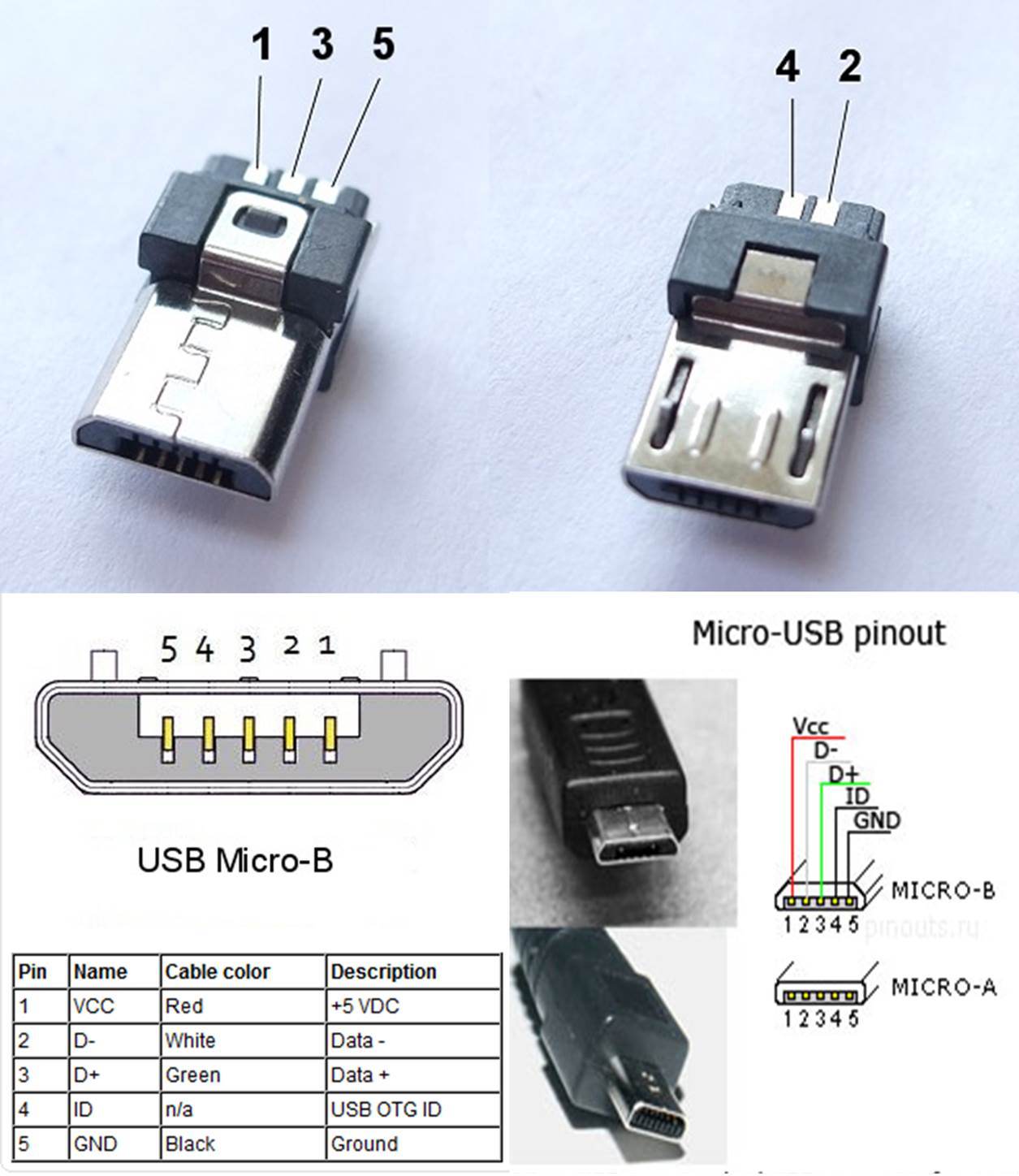
Micro B 3.0 USB Type C 3.0 The USB pinout can be divided into two parts: USB Connector Pinout and USB port Pinout. The connector here refers to the device that goes into the USB port. For example, wired Mouse is connected to the laptop by inserting its connector into the USB port.

Usb Wiring Diagram Wiki
December 10, 2018 by Dr. Steve Arar This introductory article will look at some of the most important features of the USB-C standard. Do you know your way around a USB Type-C connector? This article lays out the anatomy of the USB Type-C pinout and briefly touches on its various modes.

USB Pinout, Wiring and How It Works ElectroSchematics
The pinout explanation of USB is shown below: USB Pinout USB connectors have multiple pins, each serving a specific purpose. The two most common types are USB Type-A and USB Type-B connectors. USB Type-A typically has four pins, while USB Type-B has five pins. The basic pinout for a USB Type-A connector is as follows:

Usb Cord Wiring Diagram
%PDF-1.7 %µµµµ 1 0 obj > endobj 2 0 obj > endobj 3 0 obj >/ExtGState >/ProcSet[/PDF/Text/ImageB/ImageC/ImageI] >>/MediaBox[ 0 0 612 792] /Contents 4 0 R/Group.
multi usb port circuit diagram Wiring Diagram
USB pinout is the connector's pin configuration and how it transfers data and power. Each USB connector has a unique pinout and function. Depending on the connector, USB has four or five pins. Type-A, Type-B, Mini-USB, and Micro-USB connectors are the most popular.
.jpg)
USB Cable wiring explanation « Electrical and Electronic Free Learning Tutorials
D Mohankumar USB What is a USB? The easiest way to connect computer peripherals is through a Universal Serial Bus (USB). The USB is a plug-and-play interface between the PC and the peripherals. The main advantage of USB is that the device can be plugged in or plugged out without the need of restarting the PC
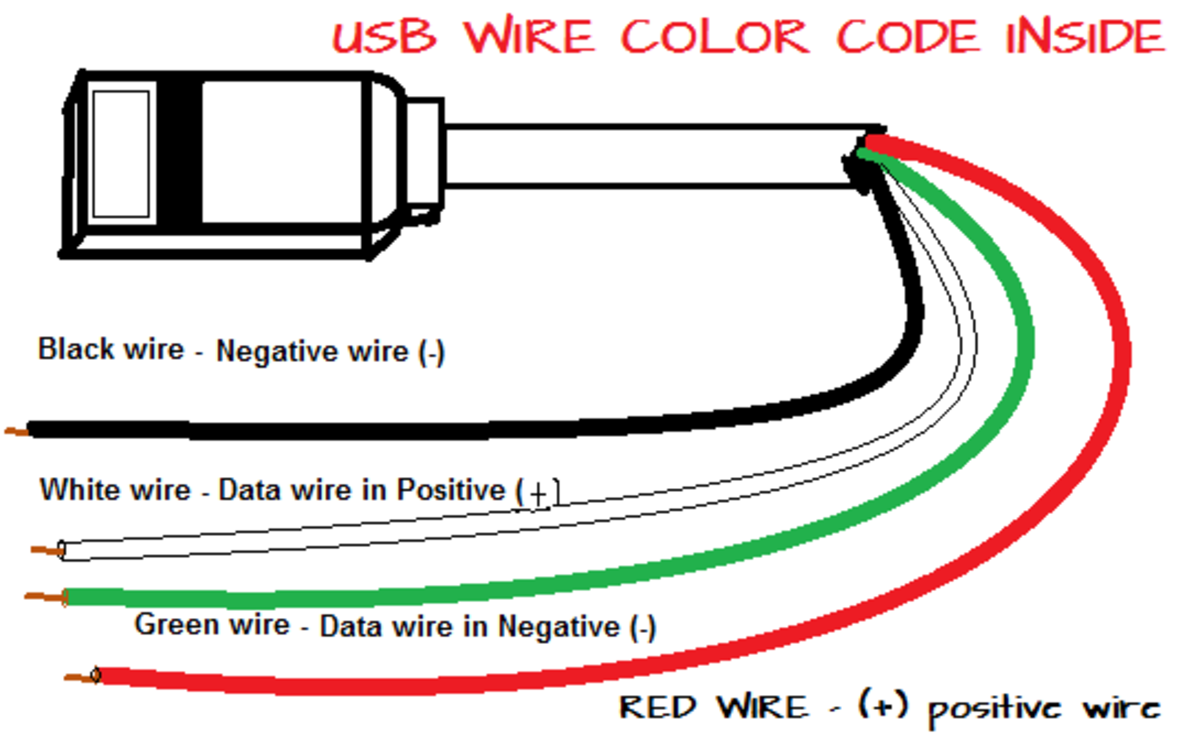
What are the color coding of the four USB wires inside a USB cable or cord
Micro USB Pinout Explained 19 Nov 2018 USB cables come with one of five different basic types of USB connector: A, B, mini B, micro B, and C. The micro connector comes standard on most non-Apple mobile phones and many other portables, though USB-C connectors are slowly replacing them in the newest generation of devices. The USB Standard