audio amplifier block diagram Wiring Diagram and Schematics
Product Highlights: 50 watts RMS x 4 at 4 ohms. 100 watts RMS x 4 at 2 ohms. 200 watts RMS x 2 bridged output. 4-, 3-, or 2-channel operation. Tri-way capable (Tri-Way crossover required) MOSFET power supply. requires 8-gauge power and ground leads — wiring and hardware not included with amplifier. two 20-amp fuses.

simple audio amplifier circuit diagram using transistor Audio amplifier
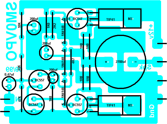
The project uses TIP41/42 as the final amplifier, the circuit is made as simple as possible with SMD Components. This amplifier is low distortion, flat and clarity sound, and good bass if you add tone control or bass booster circuit. The circuit Tested with simetrical supply, the maximum rating is 18v-0-18v transformer.

TIP 41/42 Mini Amplifier SMD Share Project PCBWay Mini amplifier, Diy audio projects
Tip 41 42 Amplifier Circuit Diagram, This 4W Audio Amplifier circuit is powered by 2 pieces of transistor Tip 41 42 Amplifier Circuit Diagram, 72+ Skema Power Amplifier Tip 41 42 Pointers for Do it Yourself Electrical Wiring and Switching Setting up or changing electrical switches and wiring is no exception.

Audio
Features ESD Ratings: Machine Model, C; > 400 V Human Body Model, 3B; > 8000 V Epoxy Meets UL 94 V−0 @ 0.125 in Pb−Free Packages are Available* MAXIMUM RATINGS THERMAL CHARACTERISTICS Maximum ratings are those values beyond which device damage can occur.
5v Transistor Audio Amplifier Circuit Diagram Wiring Diagram
TIP41, TIP41A, TIP41B, TIP41C (NPN); TIP42, TIP42A, TIP42B, TIP42C (PNP) Complementary Silicon Plastic Power Transistors Designed for use in general purpose amplifier and switching. Switching Time Test Circuit 0.06 Figure 3. Turn-On Time IC, COLLECTOR CURRENT (AMP) 0.02 0.4 6.0 0.07 1.0 4.0

Tip41 And Tip42 Amplifier Circuit Diagram
Business, Economics, and Finance. GameStop Moderna Pfizer Johnson & Johnson AstraZeneca Walgreens Best Buy Novavax SpaceX Tesla. Crypto

tip41 tip42 amplifier circuit diagram
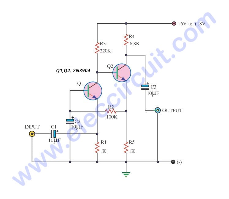
Homepage / Audio / Linear Amplifier / 4W Audio Amplifier using Transistor TIP41.. This 4W Audio Amplifier circuit is powered by 2 pieces of transistor TIP41. The circuit is very simple and incorporates darlington output transistors that will provide more than enough output current than is needed to drive a 3-ohm speaker.. 42: 34000: Hertz.

Tip 41 42 Amplifier Circuit Diagram Soft Wiring Schematic Amplifier Tip41 Tip42 This
This 4 Watt audio amplifier circuit is using TIP41 as a final stage amplifier. This amplifier circuit can provide power 4 watts at 4 ohm speaker. Transistor TIP 41 is combined with the BC547 and BC557 arranged in Darlington. The excess Darlington combination will provide current gain is much greater. This audio amplifier circuit includes a low.
4W Audio Amplifier using Transistor TIP41 Circuit Scheme
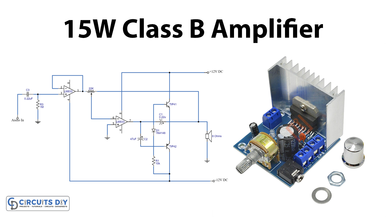
The circuit is set as a non-inverting amplifier in which the gain of IC1 is set at 14 times higher than original value. The output of the sound signal is amplified to pin 4 of IC1 to increase Q1 (TIP41) executed by R6 while Q2 (TIP42) executed by R7.

ทำขยายเสียงง่ายๆด้วยทรานซิสเตอร์ TIP41 TIP31 ใช้ไฟ 12V YouTube วิศวกรรมไฟฟ้า, แอมป์, เทคโนโลยี
They are like three soldiers, TDA2030 and two transistors ( BD908 , BD907 or TIP41 , TIP42 or 2SC1061, 2SA761 ). Their helping to increase the signal up there. TDA2030 Datasheet Audio Amplifier Circuits Pinout Others components are useful as well. However, I will explain them to you learn as follows. Figure 1.
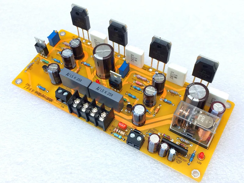
1PCS 25W 1969 Amplifier Board TIP41C Audio Tube + ON NJW0281 Output Tube Pure Class A High Power
This 4W Audio Amplifier circuit is powered by 2 pieces of transistor TIP41. The circuit is very simple and incorporates darlington output transistors that will provide more than enough output current than is needed to drive a 3-ohm speaker.. 42: 34000: Hertz: 6dB Frequency Response: 21: 62000: Hertz:. Related Posts to "4W Audio Amplifier.

Pin on Power Amplifiers
Class B amplifier circuit Class B amplifier biasing. Build a high-quality, high-efficiency audio amplifier •New parts: TIP41, TIP42 complementary power BJTs •Don't force large pins into breadboard, look at the holes and make sure the pins line up •Make sure output capacitor is oriented correctly. TIP41, TIP42 6.117 Lecture 2 (IAP.
12 voltage amplifier circuit
Component List : 1. Heat Sink2. Transistor - Tip41c Tip42c3. Capacitor - 220uf/ 16v4. Resistor - 2.2 ohm (1W) 1.

Audio amplifier using Transistor Tip41 YouTube
TIP42 is a PNP Epitaxial Silicon Transistor complementary to the TIP41. It can handle a maximum collector current (Ic) of 6A and collector-emitter voltage (Vce) of up to 100V. TIP42 also features a low collector-emitter saturation voltage, making it suitable for high-power applications. Specification of BC182:

4 Simple transistor amplifier circuit Audio amplifier, Circuit diagram, Mini
BJT transistor amplifier circuit 400w output transistors 4 tip41c quite strong and tip42c 4pcs 2 × 46 volts DC supply voltage + - symmetric power supply. Output power supply AC 12 amp amp 2x33v proposed for transformer circuit connecting to the audio input volume control stereo potentiometer 10. from 20k to do.

Pin by Dan D'Errico on 2020 in 2020 Mini amplifier, First transistor, Audio amplifier
In this video I have made a 50W audio amplifier using a pair of tip41 (npn), tip42 (pnp). The sound quality of the circuit is audible, but because it is reco.