
Rl Rc Rlc Series And Parallel Circuits Circuit Diagram
7.1: Introduction to RL and RC Circuits - Engineering LibreTexts. search Search. build_circle Toolbar. fact_check Homework. cancel Exit Reader Mode. school Campus Bookshelves. menu_book Bookshelves. perm_media Learning Objects. login Login.

RLC Circuits (13 of 19) Summary of RLC Circuit Analysis YouTube
Goal: Measure the time constant of an RC and an RL circuit, compare to the theoretical calculations. Use the schematics of figure 2 and 3 as your circuits. Figure 3: R-L circuit driven by an ideal step Voltage source. V IN can undergo a step change from zero to V IN or from V IN to zero Procedure: a.

RL, RC, and RLC Circuits Natural vs Forced Response
RC, RL and RLC Circuits . 0. 2 4 6 8 10 0 2 4 6 8 10 12 14 18 20 t V V0 1/2 V0 T1/2 Figure 4: Discharge of a capacitor. Procedure y Assemble the circuit shown in Figure 5. Function Generator. Oscilloscope R = 10 kΩ C = 0.1 μF Red Black Red Black Figure 5: Investigating an RC circuit . y With initial values R = 10 kΩ, C = 0.1 µF, and f = 100.
AllSingingAllDancing RLC circuit Engineering Teaching
An RLC circuit is an electrical circuit consisting of a resistor (R), an inductor (L), and a capacitor (C), connected in series or in parallel. The name of the circuit is derived from the letters that are used to denote the constituent components of this circuit, where the sequence of the components may vary from RLC.. RC circuit; RL circuit.
What Is The Power Factor Of Rl Circuit Wiring Diagram
RC, RL, and RLC Circuits 5 Procedure • Measure the half-life, T 1/2 and from this compute the time constant τ using Equation 3. • Compute the value of RC from component values. Note that, as described above, the square-wave generator has an internal resistance of 50 Ω. Thus

RC, RL and RLC Circuit Basic Principle and Circuit Explanations
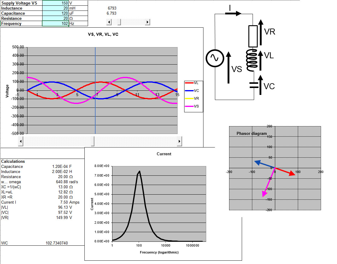
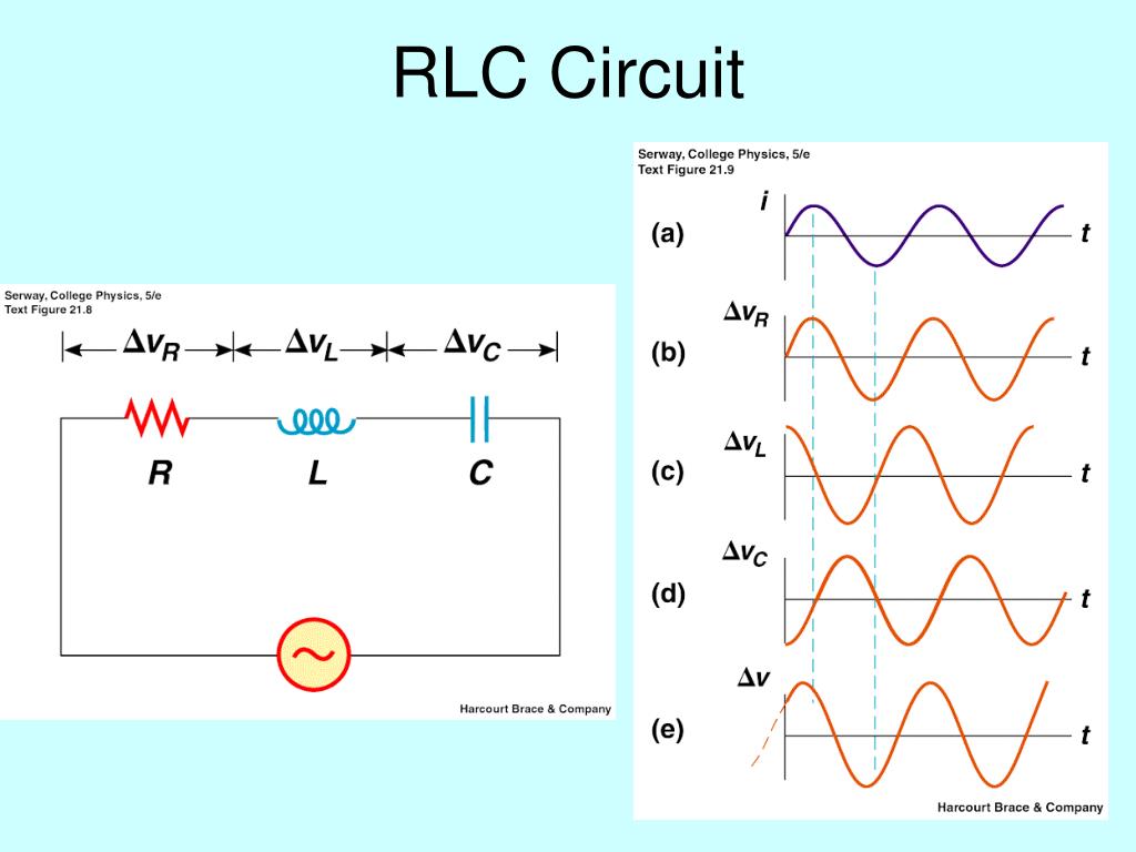
Figure 3.6.1 3.6. 1: Series RLC Circuit. We will assume that the voltage source is an audio oscillator that produces the voltage. V(t) = A cos(ωt +φ) V ( t) = A cos ( ω t + φ) We represent this voltage as the complex signal. V(t) ↔ Aejφejωt V ( t) ↔ A e j φ e j ω t. and give it the phasor representation.
RC RLC RL Series Circuits Your Electrical Guide
The RLC circuit analyzed here is the parallel form. The solution to the natural response emerges from this long analysis. The answer is not a simple single exponential equation like we get for RC, but rather a choice of three different responses ("variations") depending on the value of R, L , and C.
Offset problem in simulating current and voltage phase relation of parallel rlc circuit, Is it a
The transient response of RL circuits is nearly the mirror image of that for RC circuits. To appreciate this, consider the circuit of Figure 9.5.1 . Figure 9.5.1 : RL circuit for transient response analysis. Again, the key to this analysis is to remember that inductor current cannot change instantaneously.
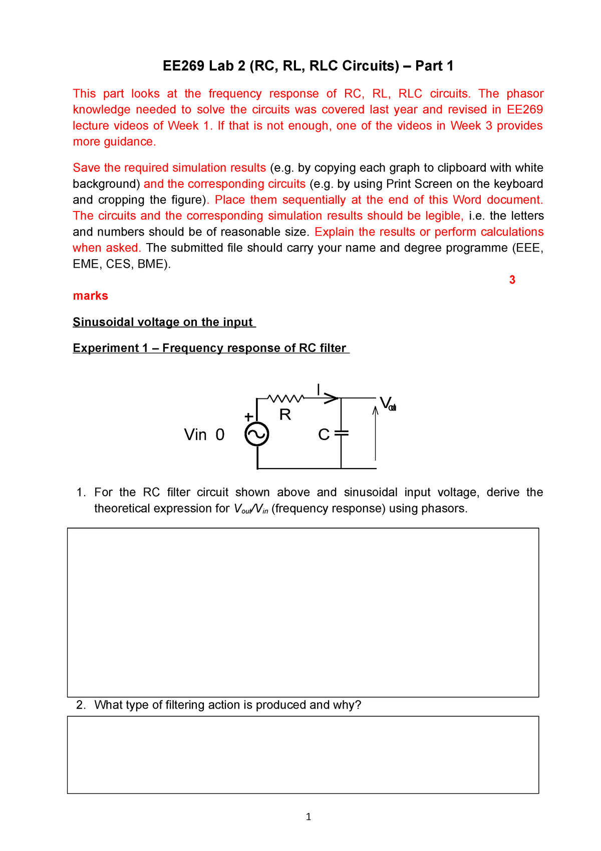
EE269 RC, RL and RLC Circuits Part 1 EE269 Lab 2 (RC, RL, RLC Circuits) Part 1 This part
The Series RLC Circuit Impulse response of RC Circuit. Let's examine the response of the circuit shown on Figure 1. The form of the source voltage Vs is shown on Figure 2. Vs R C vc +-Figure 1. RC circuit t Vp 0 tp Vs Figure 2. We will investigate the response vc(t) as a function of the τp and Vp. The general response is given by: () 1 0 t.

SOLUTION Rl rc rlc circuits Studypool
A circuit with resistance and self-inductance is known as an RL circuit. Figure 14.5.1a 14.5. 1 a shows an RL circuit consisting of a resistor, an inductor, a constant source of emf, and switches S1 S 1 and S2 S 2. When S1 S 1 is closed, the circuit is equivalent to a single-loop circuit consisting of a resistor and an inductor connected across.

Image result for rl circuit formula
Experiment 6: Ohm's Law, RC and RL Circuits OBJECTIVES 1. To explore the measurement of voltage & current in circuits 2. To see Ohm's law in action for resistors 3. To explore the time dependent behavior of RC and RL Circuits PRE-LAB READING INTRODUCTION When a battery is connected to a circuit consisting of wires and other circuit elements

Discharging Capacitor Rlc Circuit
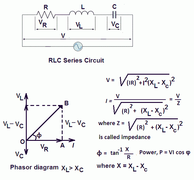
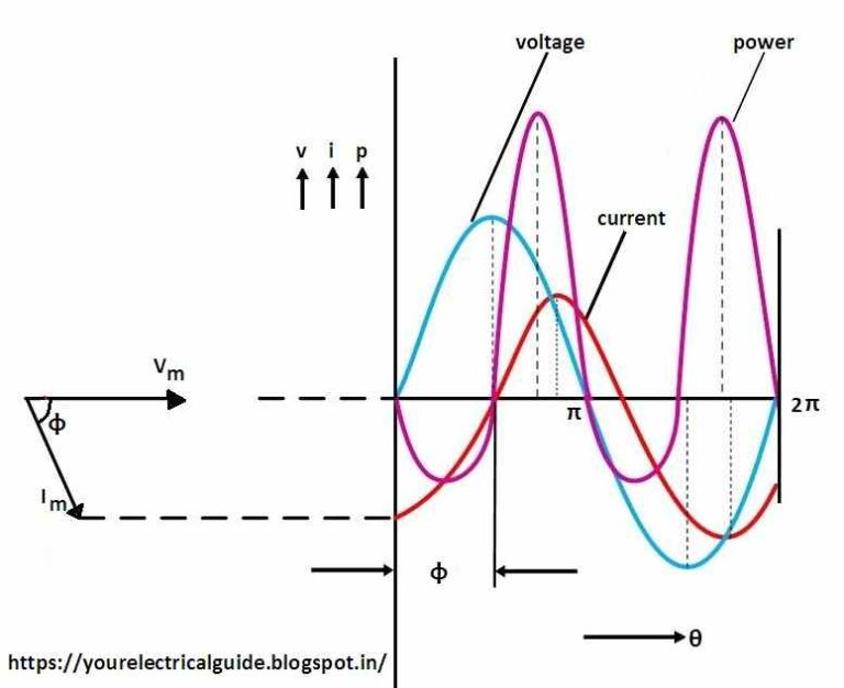
When X L > X C, the phase angle φ is positive. In this case, RLC series circuit behaves as an RL series circuit. The circuit current lags behind the applied voltage and power factor is lagging. In this case, i = Im sin (ωt - φ). When X L < X C, the phase angle φ is negative. In this case, the RLC series circuit behaves as an RC series.
RL, RC, AND RLC CIRCUITS
Two-element circuits and uncoupled RLC resonators. RLC resonators typically consist of a resistor R, inductor L, and capacitor C connected in series or parallel, as illustrated in Figure 3.5.1. RLC resonators are of interest because they behave much like other electromagnetic systems that store both electric and magnetic energy, which slowly.

Phasor Diagram For Rlc Series Circuit Circuit Diagram www.vrogue.co
Time Constant τ "Tau" Equations for RC, RL and RLC Circuits. Time constant also known as tau represented by the symbol of " τ" is a constant parameter of any capacitive or inductive circuit. It differs from circuit to circuit and also used in different equations. The time constant for some of these circuits are given below:
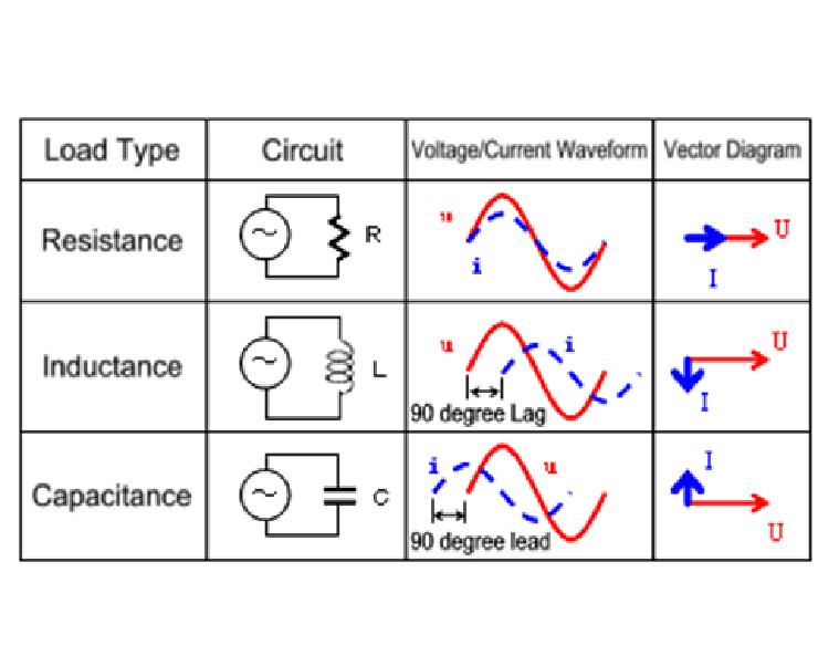
Passive Components in AC Circuits with Equations Electrical Academia
This page titled 1: Introduction to RL and RC Circuits is shared under a CC BY-NC-SA 4.0 license and was authored, remixed, and/or curated by James M. Fiore via source content that was edited to the style and standards of the LibreTexts platform; a detailed edit history is available upon request.
impedance of parallel rlc circuit
The LC circuit. In the limit R →0 the RLC circuit reduces to the lossless LC circuit shown on Figure 3. S C L vc +-+ vL - Figure 3 The equation that describes the response of this circuit is 2 2 1 0 dvc vc dt LC + = (1.16) Assuming a solution of the form Aest the characteristic equation is s220 +ωο = (1.17) Where 1 ο LC ω= The two roots are