
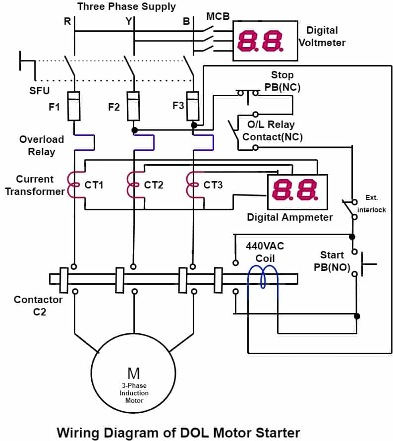
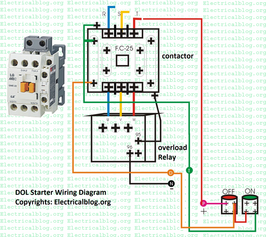
Dol Starter Power Wiring Diagram
What is Direct Online (DOL) Starter? DOL Starter (Direct Online Starter) is also knows as "across the line starter". DOL starter is a device consist of main contactor, protective devices and overload relay which is used for motor starting operations. It is used for low rating usually below 5HP motors.

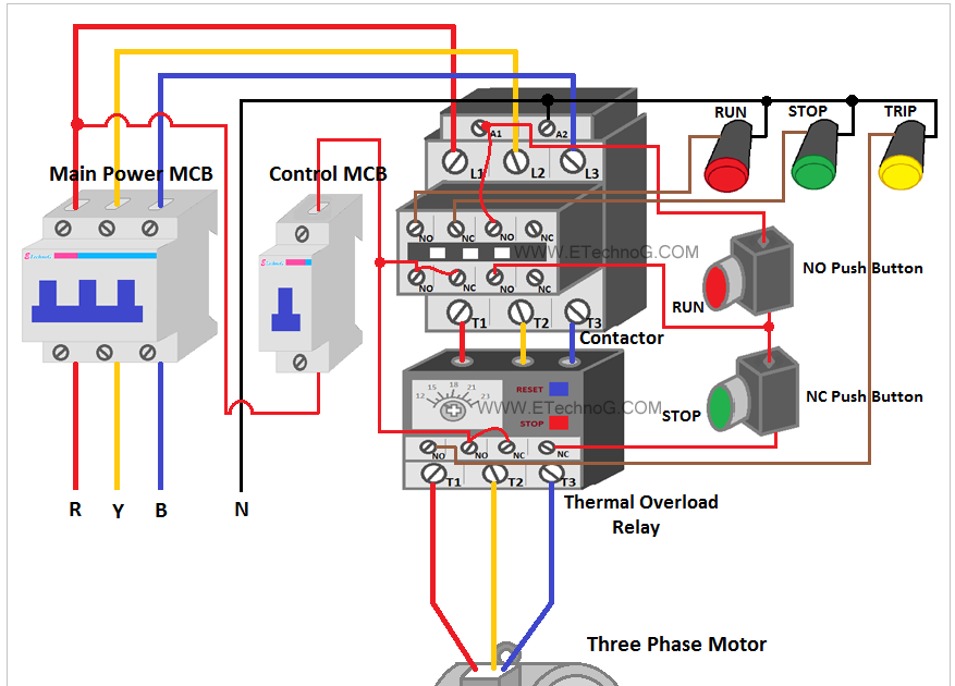
Direct Online Starter Control Circuit Diagram
Dol Control Wiring Diagrams are used to connect motors, switches, and other electrical components to form an electrical circuit. These diagrams are designed to be easy to read, so that even the novice can quickly understand the diagram's meaning. A Dol Control Wiring Diagram includes all the pieces of a circuit, including symbols to represent.

Dol Control Wiring Diagram
DOL Starter is the simplest and cheapest method used for starting a three-phase induction motor. Direct online starter is used for up to 5 HP motors. this starter is more popular due to the low price.
Starter Control Circuit Diagram
A Dol wiring diagram is a simplified schematic representation of an electrical circuit. This diagram shows both the physical components of the circuit and the way the components are connected. It also shows the direction of current flow, as well as the switches, overloads, and other safety features that may be part of the circuit.
[32+] Pin Wiring Diagram Of Dol Starter, DOL Starter Connection And Wiring Diagram With OLR
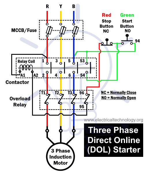
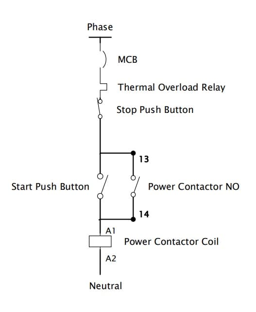
DOL starter control circuit consists of a start push button generally green, a stop push button red, a power contactor, a bimetallic overload relay, and indication lamps. The control circuit wiring diagram is shown in the below diagram
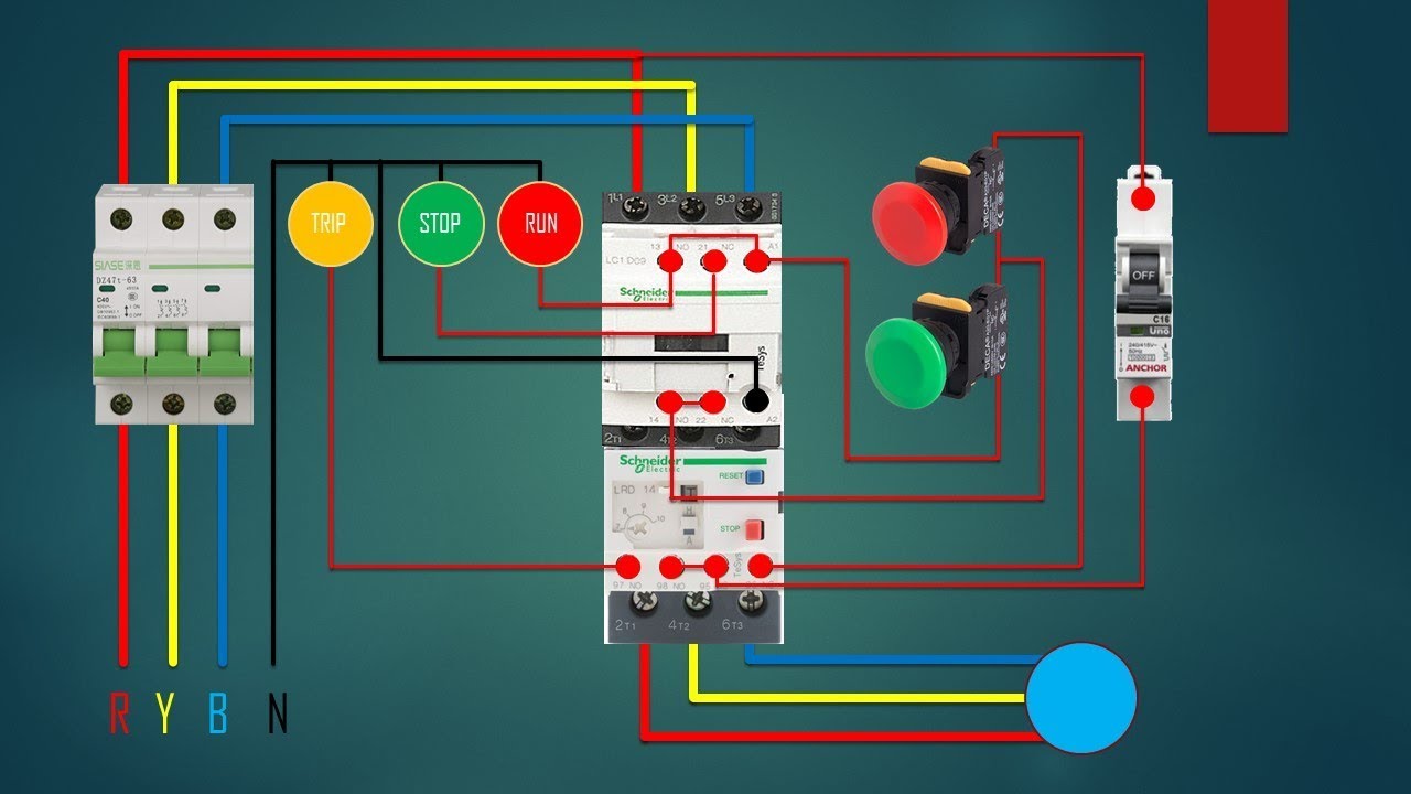
3 Phase Starter Circuit Diagram
DOL starter control wiring, Control diagram / Dol starter working animation vedio2023 01electrical maintenance 22 subscribers Subscribe 0 Share 1 view 1 minute ago Learn about a Dol.
Safety Circuit Wiring Diagram Doorbell Wiring Easy IQ2020 Main Board Replacement For A Hot
Step 3: Control Circuit Connections. Connect the control circuit wiring to the DOL starter as shown in the wiring and control diagram. to do so, Connect the digital timer's to 230V CB (usually labeled 1 & 2) and control wires to the appropriate terminals on the DOL starter as follow. 5-NO to the NO 1 - ON button and NO -13 and A1 terminal.

Dol Starter With Overload Wiring Diagram
Dol Control Wiring Diagrams come with several advantages. Not only do they help to improve the efficiency of your electrical system, but they can also save you time and money in the long run. Furthermore, Dol Control Wiring Diagrams can help to reduce risks associated with incorrect wiring.
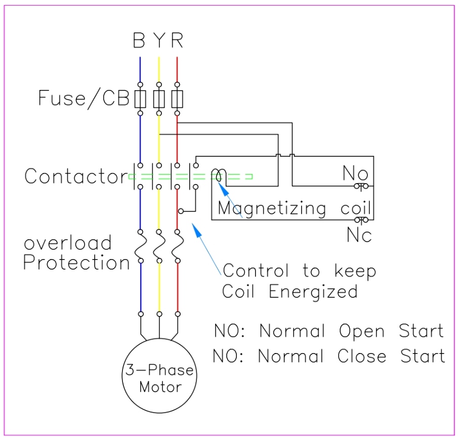
Dol Connection Circuit Diagram
Electrical Urdu tutorials 228K subscribers Subscribe Subscribed 144 Share 12K views 3 years ago #dol This video is about the 3 phase dol starter control and main wiring animation with MCCB,.
Motor Starter With Overload Protection Wiring Diagram Remote Start Collection
May 3, 2021 by Electrical4U Contents What is DOL Starter? A DOL starter (also known as a direct on line starter or across the line starter) is a method of starting a 3 phase induction motor. In a DOL Starter, an induction motor is connected directly across its 3-phase supply, and the DOL starter applies the full line voltage to the motor terminals.

Single Phase Contactor Wiring Diagram
Direct online starter is a method of starting an induction motor. The stator of the motor receives the full supply voltage in the DOL starter. Therefore, a Direct Online Starter is suitable for starting the small rating three-phase induction motors. We will also discuss the DOL power circuit diagram.

Control Circuit Diagram Of Dol Starter
The DOL and RDOL are motor starters used to control the power supply to the motor. The DOL starter controls the motor power ON or OFF and motor rotates in one direction only whereas the RDOL starter can make the motor to rotate in clockwise and anti-clockwise directions with two START buttons and one STOP button.
DOL StarterWorking, Control Circuit Wiring Diagram Electricalsblog
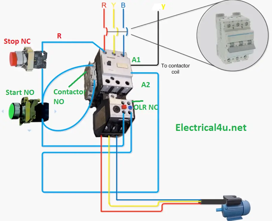
The Dol starter diagram and control wiring must be wired up correctly in order for the motor to run safely and efficiently. The diagram essentially consists of two parts: the power supply side and the control side. On the power supply side, the incoming power supply is connected to the contactor via the circuit breaker.

on video Wiring DOL STARTER with Local & Remote Start by using Salector switch / Electrical
Control wiring, as its name suggests, has the main purpose of transmitting electricity to be used for control purposes. The control wiring carries a low level of current, as not much current is required for control purposes such as activating small coil relays or feeding into PLC input cards.

Dol Motor Control Diagram
What is DOL Starter?A DOL starter (also known as a direct on line starter or across the line starter) is a method of starting a 3 phase induction motor. In a.
single phase contactor wiring diagram
A DOL starter (also known as a direct on line starter or across the line starter) is a method of starting a 3 phase induction motor. In a DOL Starter, an induction motor is connected directly.