
2 Hp Single Phase Motor Starter Diagram
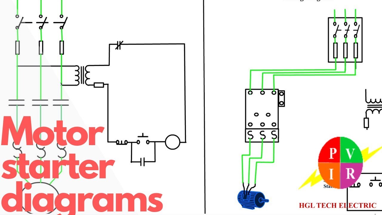
is a typical wiring diagram for a three-phase mag-netic starter. Figure 1. Typical Wiring Diagram Line diagrams show circuits of the operation of the controller. Line diagrams, also called "schematic" or "elementary" dia-grams, show the circuits which form the basic operation of the controller. They do not indicate the physical relation-

Diagram Capacitor Electric Wiring Motor 1tmv9
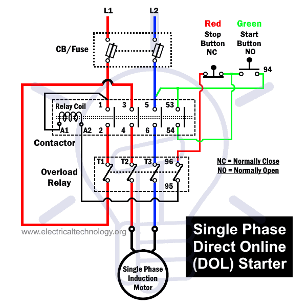
It is known as single-phase direct on-line starter. It is used in pumps, fan, cooling compressors, mixers, exhaust fan, blowers etc. the capacity rating of single-phase motor starter as.25,.5,.75, 1, 2 and 3 HP. 2- Control and connection diagram of single phase starter. 3- Working principal of single phase DOL starter.
Single Phase Motor Starter Wiring Diagram Database
Properly connect a Single Phase Motors to a three phase starter. You can find more information at http://www.electricalhelper.org/Series1000ModelNo/starters-.

Start Stop 3 Phase Motor Starter Wiring Electrical Engineering Updates
Below is the single phase motor centrifugal switch diagram. The centrifugal switch is used to connect the auxiliary winding with the capacitor and the power source. Once the speed reaches a certain value, the switch will disconnect the capacitor and the auxiliary winding from the power source.

220V Single Phase Motor Wiring Diagram Wiring Diagram
What's one way to solve the single phase problem? Build a 2-phase motor, deriving 2-phase power from single phase. A three-phase motor may be run from a single-phase power source. However, it will not self-start. It may be hand started in either direction, coming up to speed in a few seconds.

2 Hp Single Phase Motor Starter Diagram
Standard duty "START-STOP" stations are provided with the connections "A". shown in the adjacent diagram. This. connection must be removed from all but one of the "START-STOP" stations used. Heavy duty and oiltight push button stations can also be used but they do not. have the wiring connection "A", so it must.
3 Phase Auto Starter Circuit Diagram
Three-phase motors with single-phase frequency inverter should be used for frequent on/off switching. Exico Electric Motors Limited 4 Stanton Road Finedon Road Industrial Estate Wellingborough NN8 4HN www.exico.co.uk Tel 01933 277930 Fax 01933 272184.

2 HP Single Phase Motor Starter, 20 A at best price in Coimbatore ID 26276249573
Single phase motor wiring diagram with capacitor start and capacitor runIn This Video we will Learn how to connection of single phase motor with two Capacito.
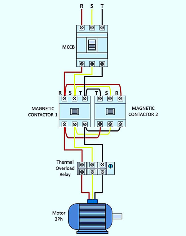
3 phase reversing motor wiring diagram
A starter is a device used in motors to start and accelerate. The function of a starter is to limit the starting current. At the time of starting the current flows through the motor is very high. The starter limits this current to a safe value. Motors below 1 HP (0.746 Watts) are directly connected to the power supply without starter because.

Single phase motor forward and reverse wiring YouTube
Maximum HORSEPOWER 3 PHASE MOTORS : Full Voltage Starting: Auto Transformer Starting: Part Winding Starting: WYE - Delta Starting: NEMA SIZE: 200V: 230V: 460V 575V: 200V

25 Amp Single Phase Motor Starter, Voltage 240 V at Rs 2211 in Surat
Single Phase Motor Single Phase Motor The electric motors that utilize the single-phase -power supply for their operation are called as Single Phase Motors. These are classified into different types, but the frequently used single phase motors can be considered as Single Phase Induction Motors and Single Phase Synchronous Motors.

3 Phase Motor Diagrams
Single Phase Electric Motor Wiring Diagrams, Terminal Connections, Frame Sizes, Other Electric Motor Information - Updated December 5, 2023. A split-phase capacitor starter electric motor may be defined as a form of a split-phase motor having a capacitor connected in series with the auxiliary winding. The centrifugal switch opens the.

2 HP Single Phase Motor Starter, 20 A at Rs 1250 in Surat ID 2850636652862
In this video, Jamie shows you how to read a wiring diagram and the basics of hooking up an electric air compressor motor. These tips can be used on most ele.

2 HP Single Phase Electronic Motor Starter (SSSA), 20 A at Rs 1120 in Ahmedabad
A motor starter is a combination of devices used to start, run, and stop an AC induction motor based on commands from an operator or a controller. In North America, an induction motor will typically operate at 230V or 460V, 3-phase, 60 Hz and has a control voltage of 115 VAC or 24 VDC.

Electric Motor Switch Wiring Diagram
For all other SINGLE-PHASE wiring diagrams refer to the manufacturers data on the motor. Diagram DD6 Diagram DD7 M 1~ LN E Diagram DD8 LN E L1 L2 L3 S/C Z1 U2 Z2 U1 Cap. Thermal contacts (TB). Single-phase motors Diag. ER 6 OEDM.. EDM Series A-2 Diags. ER 6, 7 OEN.. EN Series A-3 Diag. ER 6 OFL..ER FlexLine Series E-3/6 Diags. ER 1, 2, 4, 5

1 HP Single Phase Motor Starter, 12 A at Rs 1650 in Beed ID 16017019091
The single-phase induction motor can be made to be self-starting in numerous ways. One often-used method is the Split Phase motors. Another method is the Capacitor Start Induction Run Motors. Capacitor-Start Induction-Run Motors We know about the activity of a capacitor in a pure A.C. Circuit.