
Types Of Valves, Their Functions And Symbols Engineering Discoveries
December 21, 2017. A piping and instrumentation diagram (P&ID) is a graphic representation of a process system that includes the piping, vessels, control valves, instrumentation, and other process components and equipment in the system. The P&ID is the primary schematic drawing used for laying out a process control system's installation.

Types of Valves (P&ID symbols) ? REFINERY OIL AND GAS
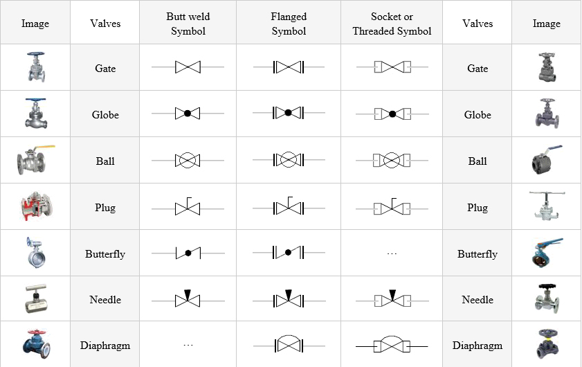
Isometric Drawing Symbols for Valves Buttweld Ball Valve Buttweld Butterfly Valve Buttweld Check Valve Buttweld Gate Valve Buttweld Globe Valve Buttweld Needle Valve Buttweld Plug Valve Buttweld Three Way Valve Buttweld Y Type Valve Flanged Ball Valve Flanged Bottom Valve Flanged Butterfly Valve Flanged Check Valve Flanged Diaphragm Valve
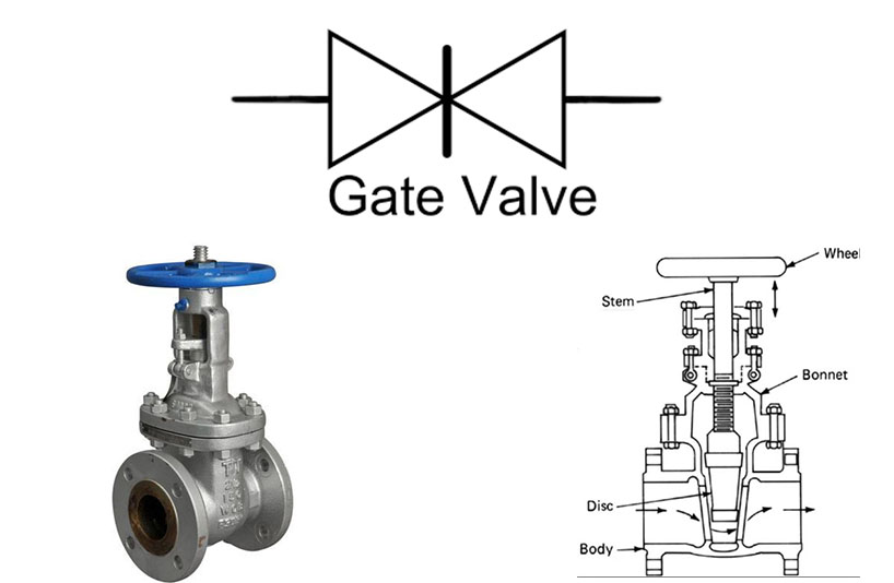
Gate Valve Symbol
Gate Valve symbol. Globe Valve symbol. Check Valve symbol 1
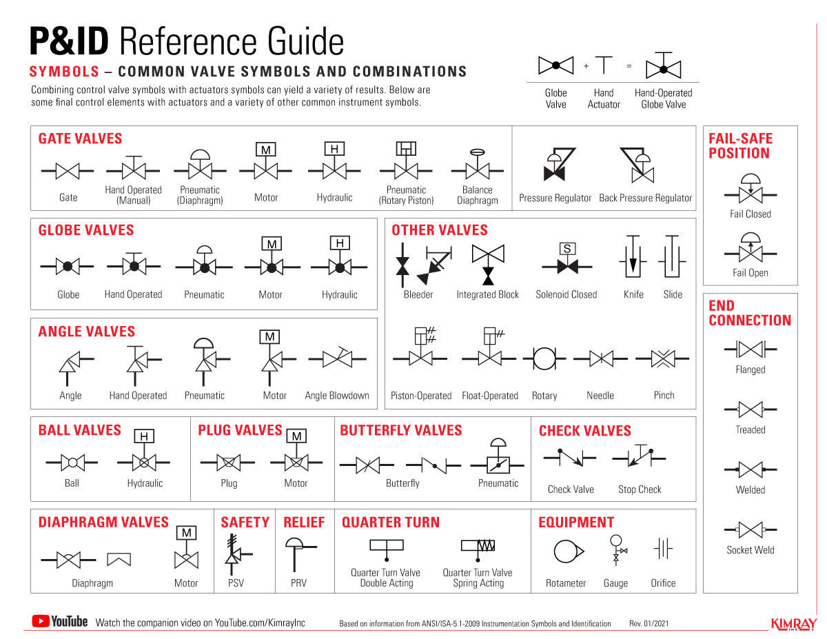
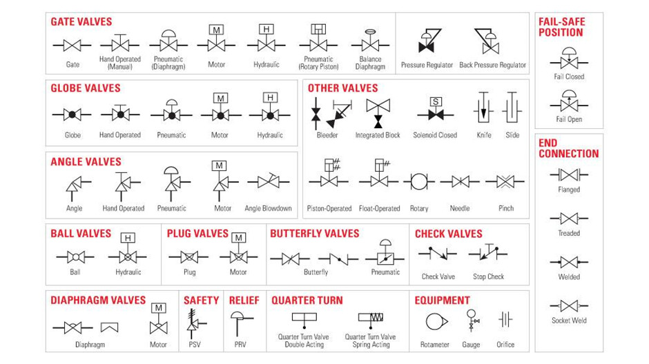
The Most Common Control Valve Symbols on a P&ID Kimray
Valve Symbols. Valves are used to control the direction, flow rate, and pressure of fluids. Figure 1 shows the symbols that depict the major valve types. It should be noted that globe and gate valves will often be depicted by the same valve symbol. In such cases, information concerning the valve type may be conveyed by the component.

symbols of valve and fitting Valve Actuator
A gate valve, also known as a sluice valve, is a valve that opens by lifting a barrier (gate) out of the path of the fluid. Gate valves require very little space along the pipe axis and hardly restrict the flow of fluid when the gate is fully opened. The gate faces can be parallel but are most commonly wedge-shaped (in order to be able to apply.
Control Valve Symbols Valves Industrial Automation, PLC Programming
A gate valve is a control valve that either allows media to flow through unobstructed or stops the fluid flow. The main advantage of a gate valve is the straight-through unobstructed passageway, which induces minimal pressure loss over the valve. The unobstructed bore of a gate valve also allows for a pig's passage in cleaning pipe procedures.
Control valve symbols in P&id Valves Industrial Automation, PLC
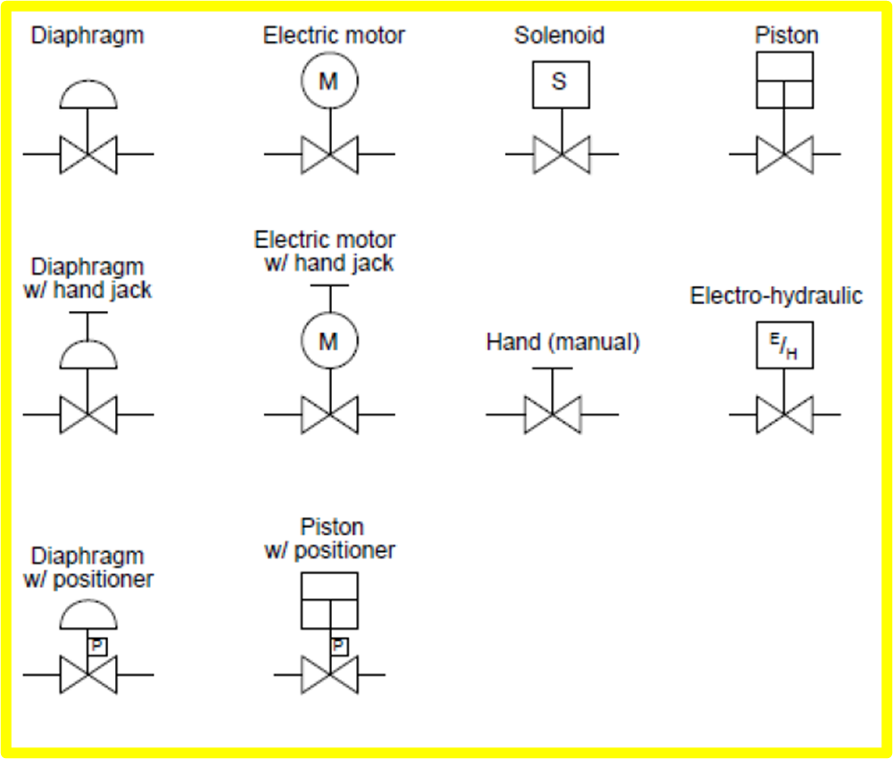
a. Globe valve g. Relief valve b. Gate valve h. Rupture disk c. Ball valve i. Three-way valve d. Check valve j. Four-way valve e. Stop check valve k. Throttle (needle) valve f. Butterfly valve l. Pressure regulator EO 1.2 IDENTIFY the symbols used on engineering P&IDs for the following types of valve operators: a. Diaphragm valve operator b.
The Most Common Control Valve Symbols on a P&ID Kimray
Valve symbols are used to signify the pressure, flow and direction of fluids through a valve. These illustrations, commonly referred to as Piping and Instrumentation Diagram (P&DI) symbols, may vary slightly between organizations but similar sketches are used to identify types and position of valves. Valve symbols generally describe the.

Valve Symbols in P&ID Ball Valve, Relief Valve and more
The symbology for the identification of the measurement and control instrumentation on the flow and process diagrams and on the P&ID (Piping & Instrument Diagram), commonly called P&I (Piping & Instrumentation), is generally compliant with the Standard ISA (Instrumentation Society of Automation) identified as S.5, that is composed of identificat.
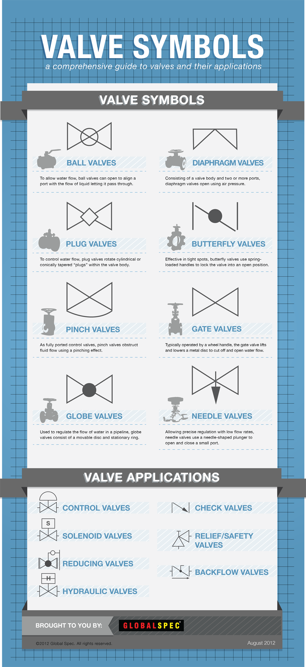
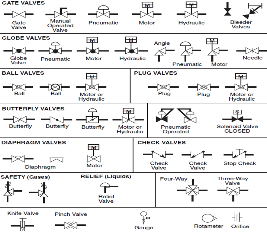
Valve Symbols
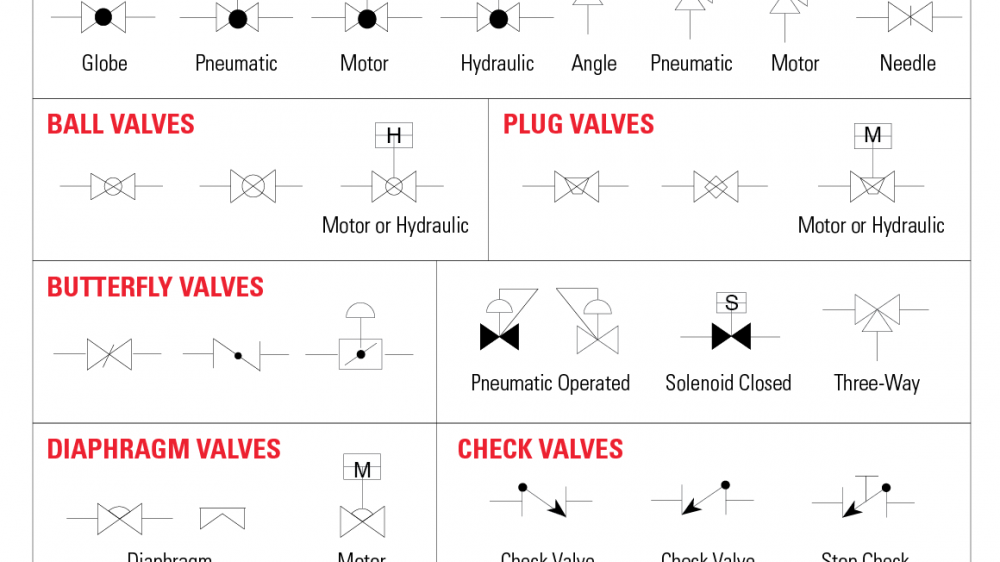
What common symbols are included? Gate Valves; including manual operated, pneumatic, motor, hydraulic and bleeder. Glove Valves; including pneumatic, motor, hydraulic, angle and needle. Ball Valves; including motor and hydraulic. Plug Valves; including motor and hydraulic. Butterfly Valves Diaphragm Valves Check Valves Safety (Gases)

Valve Symbols Free CAD Block Symbols And CAD Drawing
SYMBOLS VALVES valve is a mechanical device that controls the flow of fluid and pressure within a system or process. valve controls system or process fluid flow and pressure by performing any of the following functions: Stopping and starting fluid flow Varying (throttling) the amount of fluid flow Controlling the direction of fluid flow
Valve Sign Symbols The Engineering Concepts
Some of the most common 2-way valve symbols are ball valves, butterfly valves, plug valves, gate, valves, etc. Examples of these symbols can be found further down in this article. Figure 2: A gate valve with the direction of flow running from left to right. 3-way and 4-way valves
gate valve isometric symbol Valve symbols what they look like & their
A P&ID is a detailed, visual representation of a process system. P&IDs include standard symbols that explain: Component identification. How instruments are connected. Where instruments are located. The instruments' function within a process. The symbols for these components aren't drawn to scale and aren't intended to be dimensionally.

GATE VALVE Different types of gate valves Advantage, Disadvantage
Symbols include: gate valve symbol globe valve symbol ball valve symbol plug valve symbol butterfly valve symbol diaphragm valve symbol check valve symbol DOWNLOAD THIS CHART An engineer may also include specific details below the control valve symbol. These details may include the size, function, pressure rating, and connection type of the valve.
Valve Symbol Saba Dejlah
A gate valve is one of the most used types of valves in a Power Plant. These valves operate by lifting a gate up and down to open or close the valve, thus controlling flow through the system. Globe A globe valve operates by a barrier, such as a plug, moving up or down to seal a stationary ring.

check valve symbols on drawings Symbols engineering process diagram
Gate Valves. A gate valve will open or cut off the flow of water through a pipe. They typically have a wheel handle that gets turned to operate the metal disk that blocks the flow. Its symbol looks like the outline of a bowtie with two straight lines crossing each other to form an "X". Then two vertical lines connect the ends to create an.