Simple timer circuit using Ic 555
in this video, I will show you how to make a time circuit using a transistorBuy Electronic Component From Here:- https://www.electronicspices.com/If u really.

TIMER CIRCUIT how to make simple timer circuit using one transistor YouTube
10 Best Timer Circuits using IC 555 Last Updated on January 3, 2024 by Swagatam 70 Comments The circuits explained here are 10 best small timer circuits using the versatile chip IC 555, which generates predetermined time intervals in response to momentary input triggers.
Basic 555 Timer Circuit
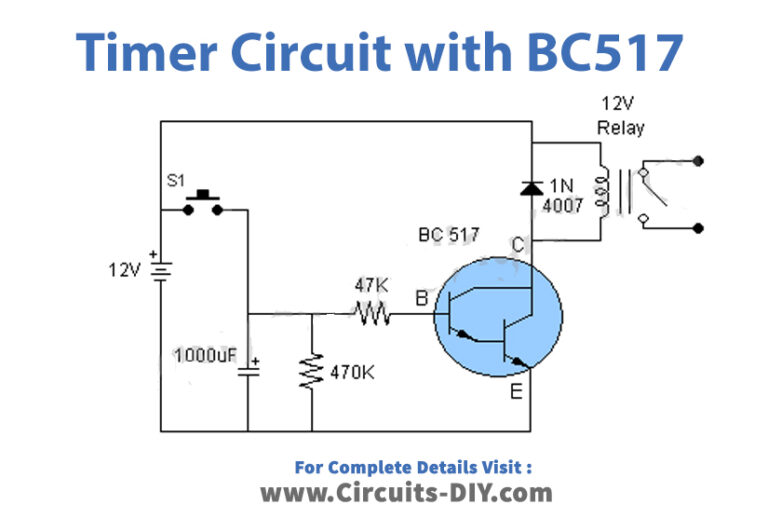
Here, the timer is a very simple circuit, working by using just one or a pair of transistors. this circuit serves its purpose of time delays operation of a device. The timer circuit is made with a number of different schematics which are explained as follows. Buy Now Hardware Components The following components are required to make Timer Circuits
Simple Delay Timer Circuits Explained Homemade Circuit Projects
555 Circuits Part 1 - The Fastest 555 Oscillator. By varying the value of either R or C the 555 astable multivibrator circuit can be made to oscillate at any desired output frequency. But what is the maximum frequency of oscillations we can produce from a single 555 timer chip. To get the 555 to operate at its highest frequency in this 555.
Simple Delay Timer Circuits Explained Homemade Circuit Projects
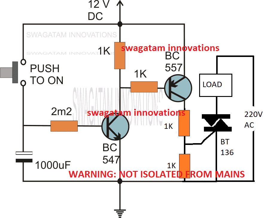
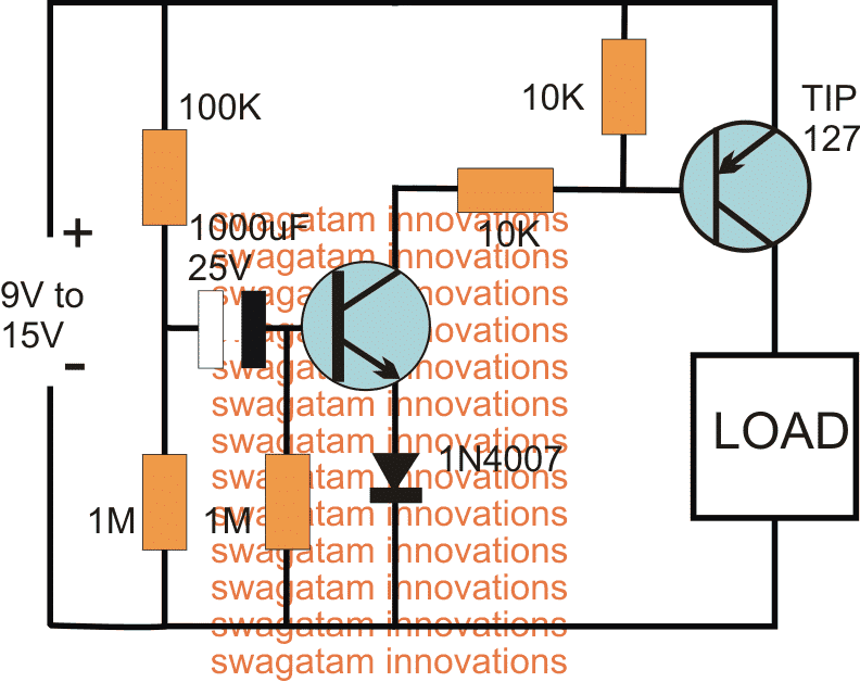
In this post we discuss the making of simple delay timers using very ordinary components like transistors, capacitors and diodes. All these circuits will produce delay ON or delay OFF time intervals at the output for a predetermined period, from a few seconds to many minutes. All the designs are fully adjustable. Importance of Delay Timers
555 Timer Schematic / 555 Timer Tutorial The Monostable Multivibrator Walton Foodursh55
The timer circuit is used to trigger the counter IC, which in turn advances each count on the seven segment LED display LT543. The complete details about the circuit and its circuit diagram are given in the original article. 2. Flasher Circuit using NE 555
Simple Timer Circuit Diagram Circuit Diagram
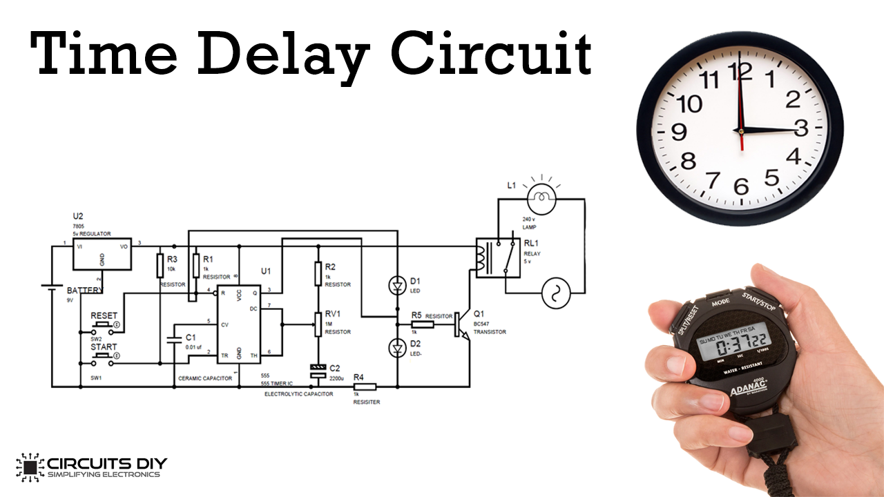
1 Minute Timer Circuit: 5 Minutes Timer Circuit: 10 Minutes Timer Circuit: 15 Minutes Timer Circuit: Working of Timer Circuit Application In the era of technologies, everyone is taking the help of machines to simplify their life. Timer circuits ease your day to day tasks in many ways by initiating or doing it in a definite time interval.

A Simple Timer Circuit Diagram with IC 555 ETechnoG
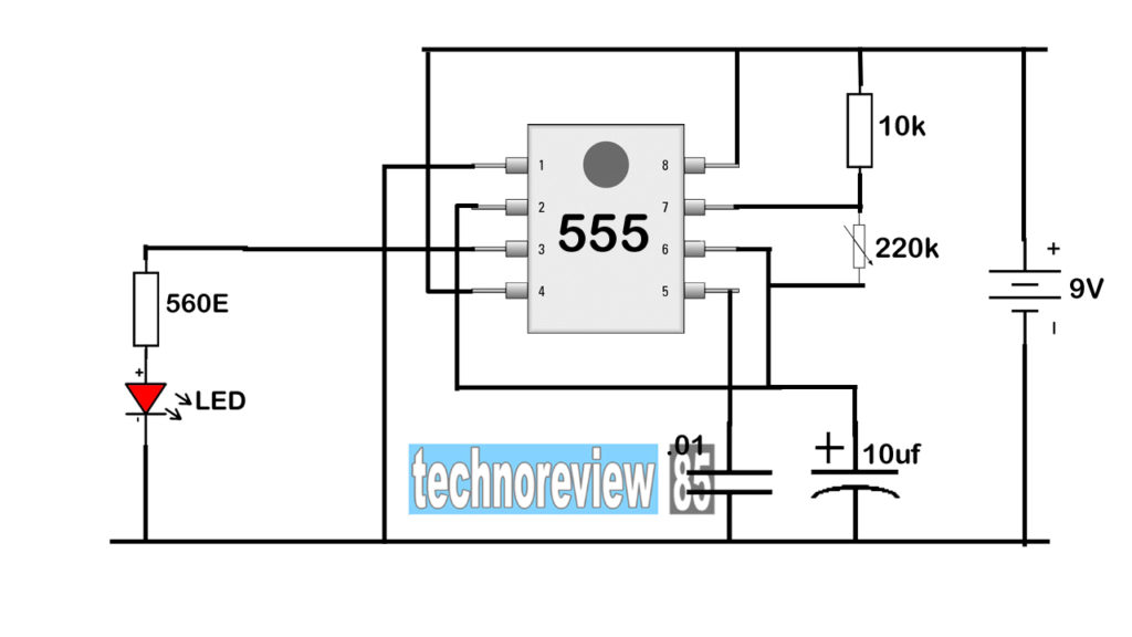
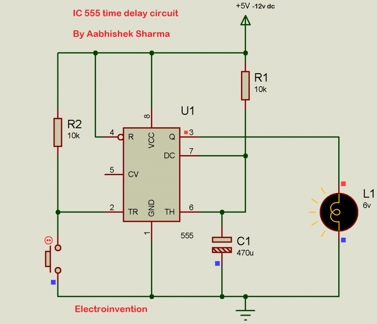
15 Minute Timer Circuit 15*60 = 1.1*R1*1000 uF R1 = 818.2 k ohm As per above calculations, for a 15 minute timer circuit, we need the value of resistor to 818.2k ohm. We should note here that we have used LED at reverse logic, means when OUTPUT pin 3 is low, LED will be ON, and when OUTPUT is HIGH then LED will be OFF.
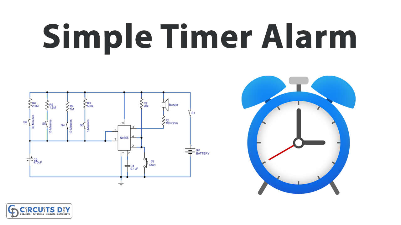
Simple Timer Alarm Circuit using IC 555
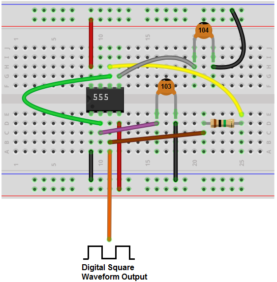
Step 15: Going From Breadboard to Circuit Board. The next task, should you choose to accept it, is to make the timer permanent by putting onto a PC board. The easiest way to do so is to keep the circuit on the breadboard and build a second one on the PC board.
Top 3 Simple Timer Circuits
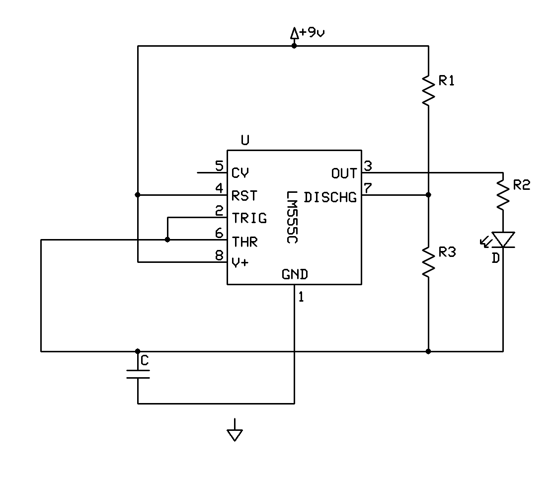
555 Timer Circuits. The 555 Timer IC is a popular 8-pin Integrated circuit chip that can be used in a variety of timing and pulse generation applications. The IC can operate in three different modes such as Astable, Monotstable and Bistable, because of which it can be adapted into many types of circuit designs like time delay circuits, pulse.

How to Make a Simple Timer Circuit Using IC 555 Circuit Diagram Centre
Simple 555 Timer Circuits & Projects March 18, 2017 By Anusha 555 timer is an industrial standard IC existing from early days of IC. Its name is derived from three 5K ohm resistors ,connected in series used in it.The timer IC can produce required waveform accurately. 555 timer was first introduced by signetics corporation in 1971 as SE555/NE555.

555 Timer Basics Astable Mode
The 555 timer IC is a very cheap, popular and useful precision timing device which can act as either a simple timer to generate single pulses or long time delays, or as a relaxation oscillator producing a string of stabilised waveforms of varying duty cycles from 50 to 100%. The 555 timer chip is extremely robust and stable 8-pin device that.
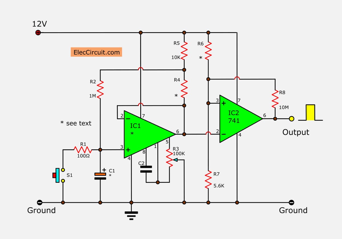
Simple long duration timer
June 4, 2021 by Øyvind Nydal Dahl In this 555 Timer tutorial, you'll learn how to use the 555 timer to do fun things. One of the first things many do with it is to create a blinking light. But that's just one simple example of the many things you can do with this chip.
IC 555 Delay Timer circuit Easy timer circuit on off delay circuit
Adjustable Timer Circuit Using IC 555 Last Updated on June 25, 2022 by Swagatam 155 Comments IC 555 adjustable timer explained here can be adjusted from any time delay 1 second to 3 hours for operating any load through a relay control The produced time delay is fully adjustable and the user has the freedom to set the time period as desired.
How to Build a Clock Circuit with a 555 Timer
in this video, I show how to build a simple delay timer circuit. With such timer you'll be able to turn a light bulb or any other appliances on or off, for a.
Simple 2 minute Timer Circuit for your DIY Digital Lab
Simple Adjustable Timer Circuit with 555 IC Using simple 555 timer we can design an adjustable timer switch. This circuit is flexible to adjust required time. Circuit Diagram Components 555 timer Electrolytic capacitor - 470 uf ceramic capacitor - 0.1nF Resistors 120k ohm 10k ohm Relay -12v Push button Working