
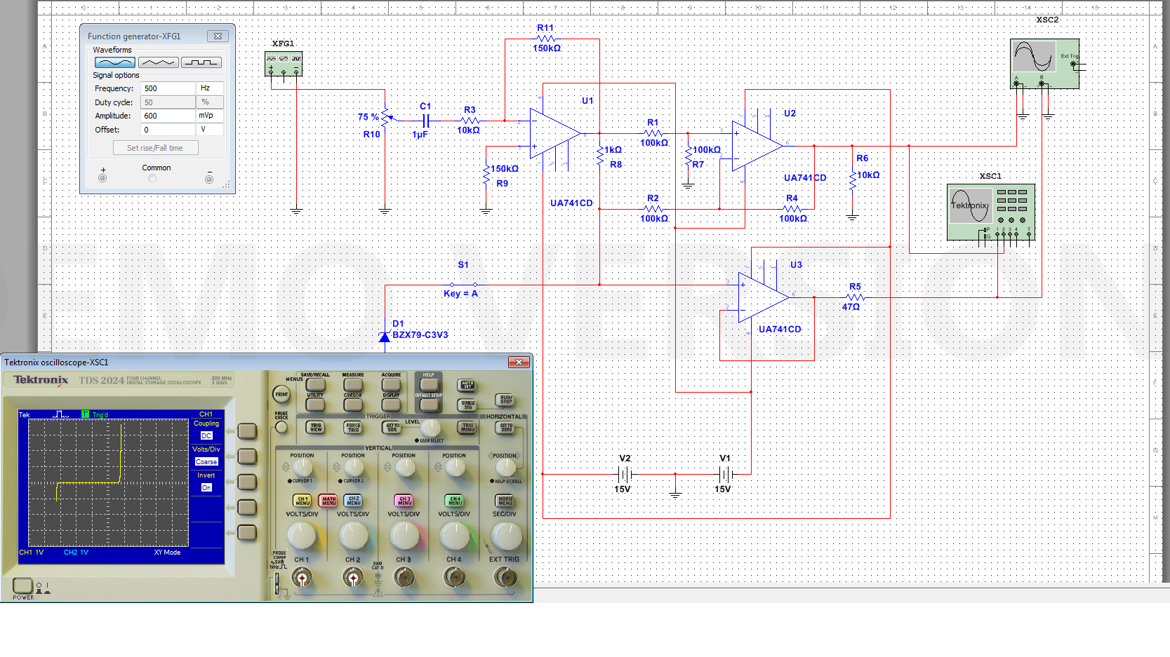
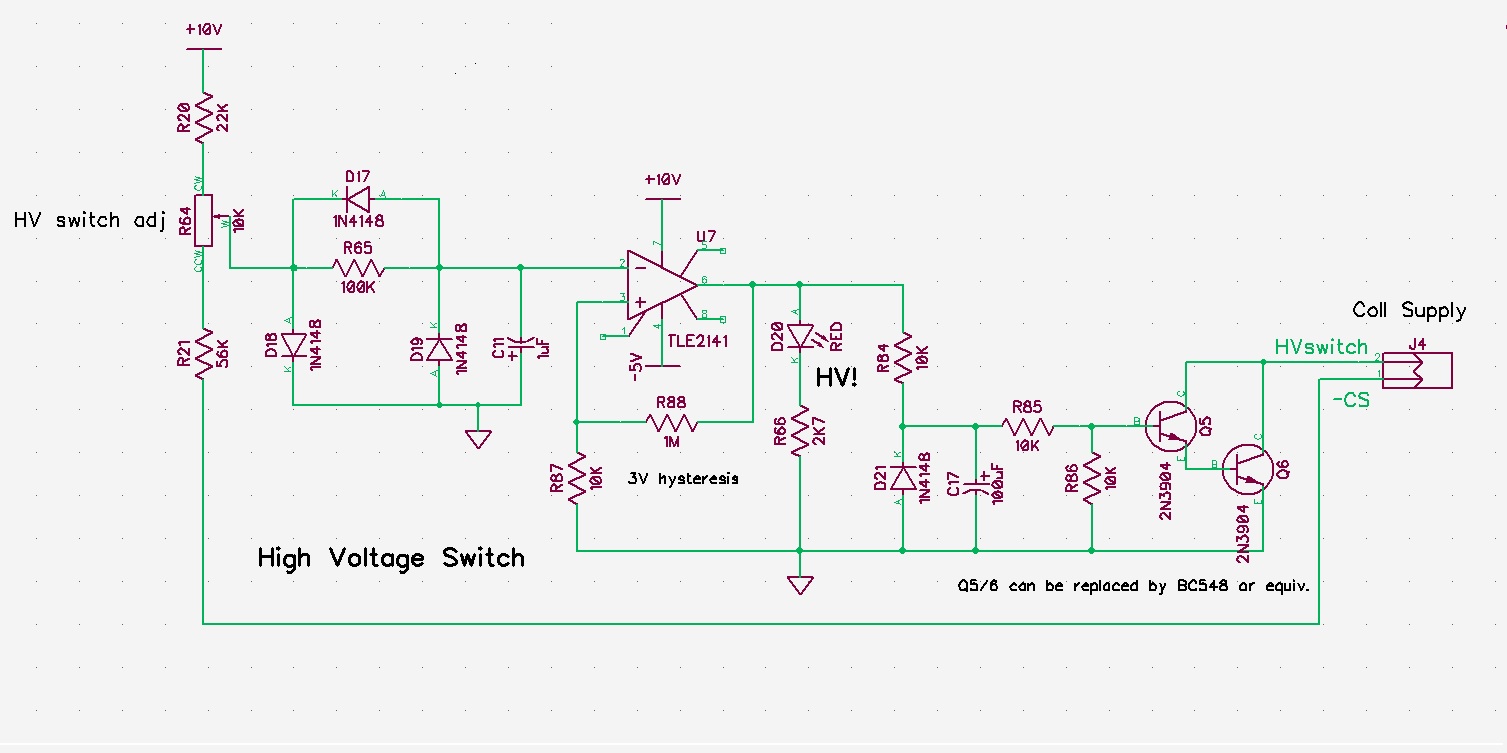
Curve Tracer Schematic
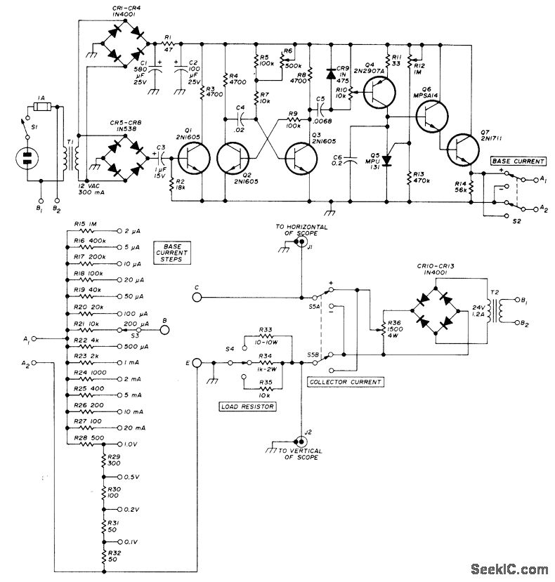
[VERTICAL DEFL.] The 3rd transformer is used to generate an impulse to trigger the counter (74HC191) which counts from 0 to 7. The output of this counter forms with an R2R-network a staircase which is amplified to 7 Vpp. (adjusted with R20). This staircase is inverted with IC6a and another relais switches between the polarity (NPN or PNP).
Eddy Simple but effective Transistor Curve Tracer circuit.
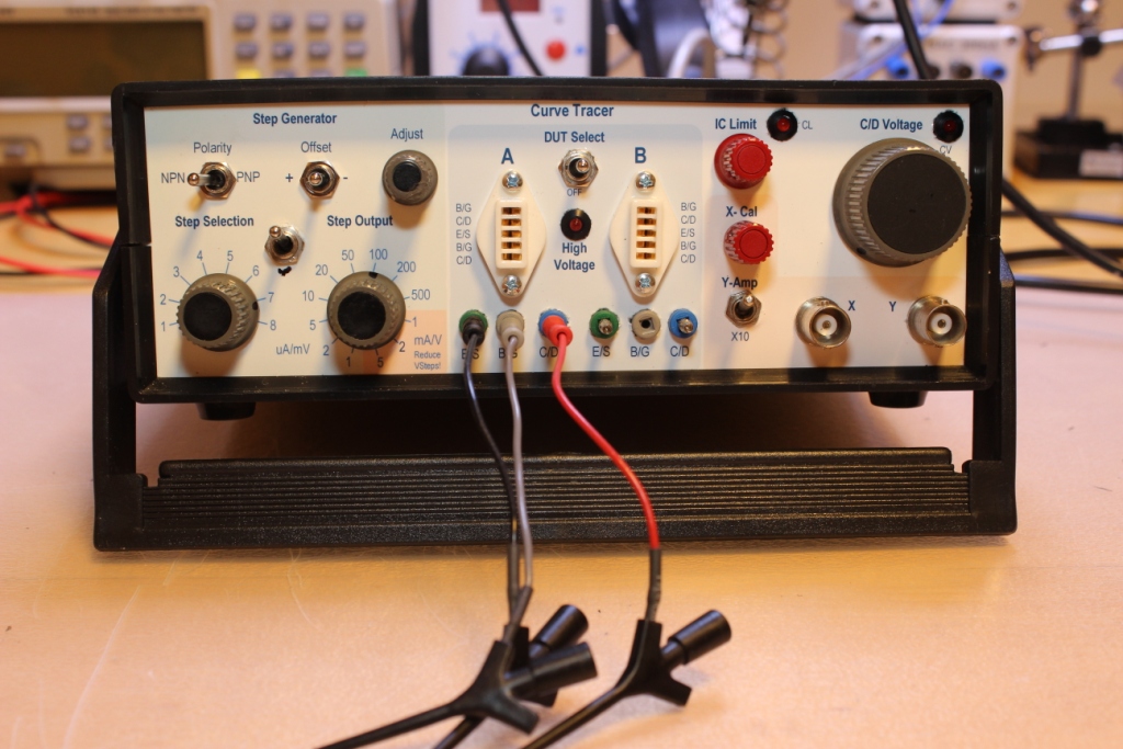
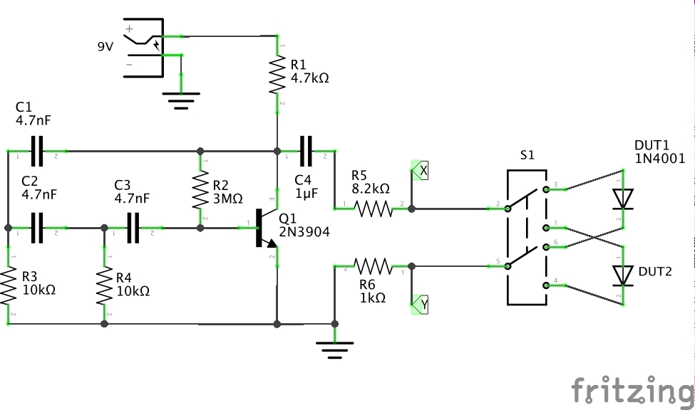
Inspired by Stoneslice's tutorial, Paul Gallagher ( tardate) has developed further on the Curve Tracer by using a simple DC Powered oscillator to drive a test signal across the device under test, instead of relying on an AC power supply. Paul also added a DPDT switch to toggle and compare two devices under test.
Paul's DIY electronics blog Building A Curve Tracer
Simple but effective Transistor Curve Tracer circuit. This curve-tracer uses only 6 transistors and produces a beautiful curve display on an oscilloscope in X-Y mode. And it doesn't even matter which transistors you use to build it with!! I build it up on a bread-board first and it works very well!

Paul's DIY electronics blog Building Another Curve Tracer
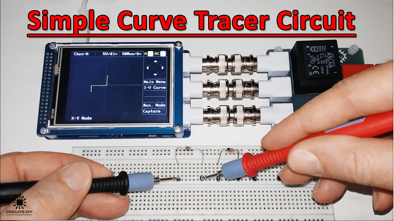
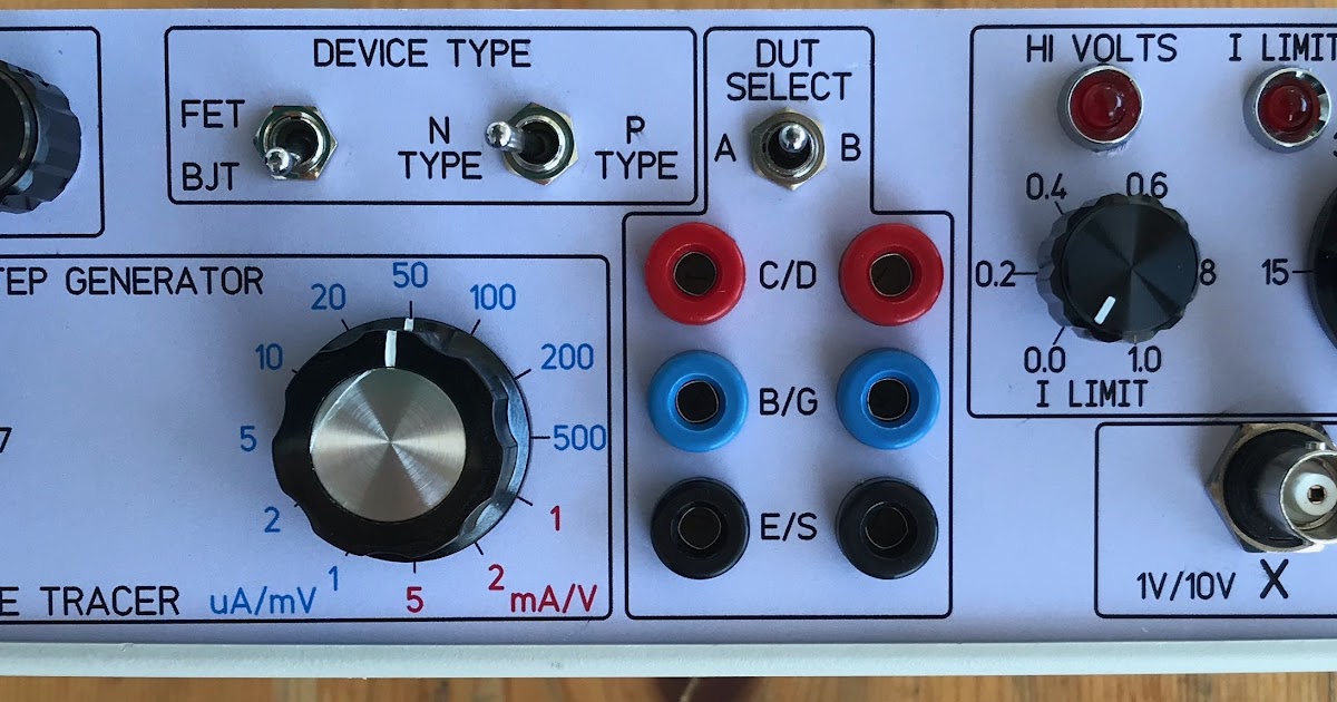
Step 1: How to Use It When you switch on the curve tracer, the main menu screen is displayed. Select the kind of device by touching one of "PNP NPN", "MOSFET" or "JFET". You can test diodes in the "PNP NPN" mode. Put the Device Under Test (DUT) into the ZIF socket. The menu screen shows you which pins to use.
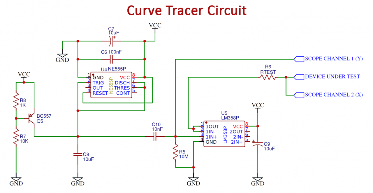
Simple Curve Tracer Circuit for Resistor, Diode, and Transistor
The output of the curve tracer can be read o of two test points and an oscilloscope in X-Y mode can be used to display the curves generated. This allows for the easy export of the characteristic curves through the oscilloscope's USB port. 2 Project Overview Our project's circuit can be split into three main parts - the device identi cation.
CURVE_TRACER Basic_Circuit Circuit Diagram
In January 2021, I blew-up (through my own haste and stupid fault, I connected an incorrect external transformer) my Curve Tracer (CT) and damaged so many parts that it is difficult to get it back to where it once was. There are a number of reasons why I have decided to build a new one.
Simple Curve Tracer Circuit for Resistor, Diode, and Transistor
The curve tracer testing is a diagnostic tool used to measure the electrical performance of an electrical system. It measures inductance, resistance, and capacitance by measuring voltage and current in response to a range of test inputs. The curve tracer is a testing device that measures the performance of cables and wires about the three.
Arduino based component curve tracer Hackaday.io
Attach your diode to the input connections, as described in the blinking box at the top of the screen, and press the Get Characteristic Data button. The diode characteristic will be plotted twice: on log/lin axis in the upper plot and lin/lin axis in the lower plot. The Curve Tracer will acquire and plot the diode charac-teristic.
Project Curve Tracer Design Refinement
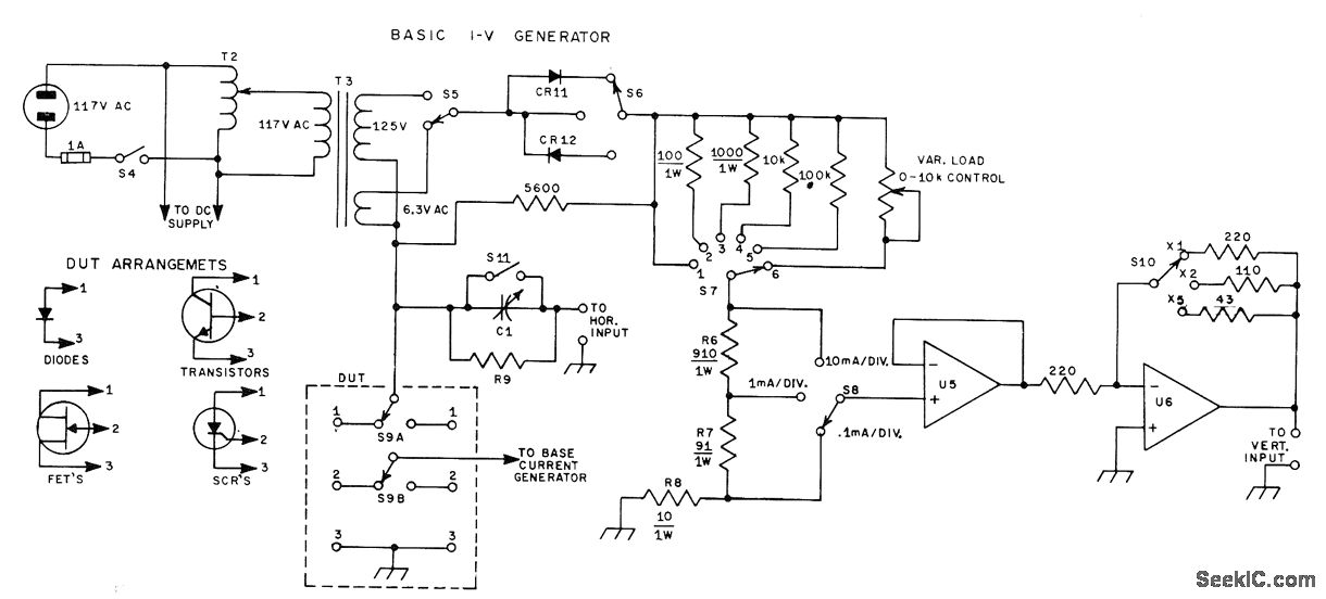
Sometimes called a VI curve tracer, an IV curve tracer, or an oscilloscope Octopus, this general-purpose instrument is invaluable in troubleshooting (Figure 1). The Octopus generates AC excitation across its two leads and then displays a voltage vs. current plot in real time.

Tube Curve Tracer 10 Steps Instructables
Figure 1 Schematic of the Curve Tracer Testing Device R1 To Vertical +---/\/\----+-------+-------> Scope Output | 220 | | ("Y") 6.3V | Ohm | \ XMFR | >>o--)||( | )||( CT | 117VAC )||(----+ )||( >>o--)||( | | R3/1K \Ohm | \ +---+---> To Scope GND R2/100 | \Ohm | / +===> Black Probe |
Paul's DIY electronics blog Building a Curve Tracer Version 2
Curve tracers are measurement instruments used to characterize devices such as transistors and diodes. New ones cost thousands of dollars. Even old Tektronix 575 transistor curve tracers, implemented with electron tubes and found on the surplus market, cost $75 or more.
TRANSISTOR_CURVE_TRACER Basic_Circuit Circuit Diagram
The main benefit to those types of curve tracers is the fact they can make the classic stacked I_C vs. V_CE graphs that you see with all BJT (Bipolar Junction Transistor) datasheets You can also do it with this one, but you'd need to combine different scope images at various Volt/Amperage settings.
Paul's DIY electronics blog Building A Curve Tracer
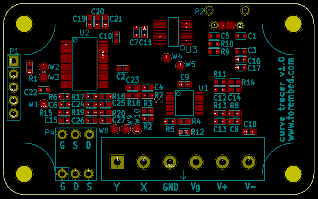
Pauls-Curve-Tracer. Schematic and PCB files for a PCB version of Paul V's curve tracer circa 2017. About. Schematic and PCB files for a PCB version of Paul V's curve tracer circa 2017 and 2020 Resources. Readme License. MIT license Activity. Stars. 7 stars Watchers. 3 watching Forks. 5 forks
DIY Generic Curve Tracer
Building a Curve Tracer - Version 3. Mark is using Altium Designer to generate the schematics and layouts, and I had been using DipTrace, that I used for several years, to import the Altium files. This was a very cumbersome process that needed a lot of tweaks and changes. With the recent version of KiCad 6, there is now an import.

CURVE_TRACER_SCHEMATIC EasyEDA open source hardware lab
Curve tracing is essentially a means of making a graph of current (I) versus voltage (V) called an I-V curve, to display the basic characteristics of an electronic device. I-V curves of the components are helpful in understanding their limitations and nonlinear operation.
Full on transistor/fet curve tracer under Repositorycircuits 27230 Next.gr
1 7 7 Team ( 1 ) Donna LaRocco Join this project's team Video about the curve tracer completed project hardware octopus curve tracer This project was created on 01/05/2023 and last updated a year ago. Description While I have an octopus I purchased on Ebay, I really wanted to make my own with a couple bells and whistles.