
Hydraulic & Electric Symbols Valve Technology & Engineering
i You can find more technical information at www.hansa-flex.com/en/services/technical_information SYMBOLS FOR HYDRAULICS www.hansa-flex.com/technical-information.
Hydraulic Symbols
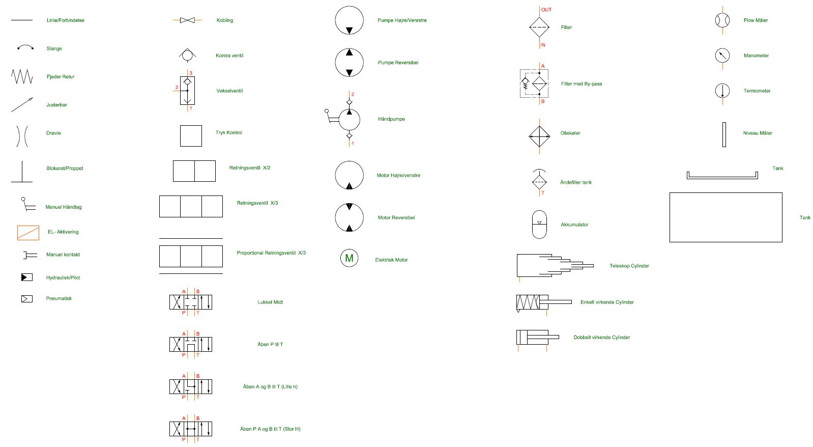
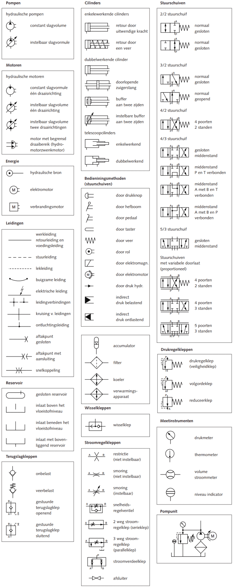
Hydraulic Symbols. Hydraulic circuits can be comprised of an infinite combination of cylinders, motors, valves, pumps and other equipment connected via hydraulic pipes and tubes. The complexity of these components are difficult to represent fully, so a family of graphic symbols have been developed to represent fluid power components and systems.

Pneumatik symbole pdf
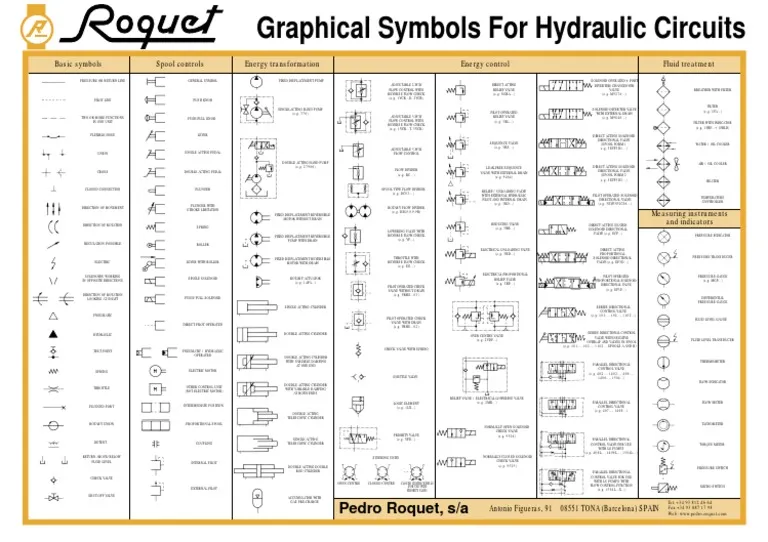
Hydraulic & Offshore Supplies BASIC SYMBOLS RETURN LINE LINE TWO OR MORE FUNCTIONS ONE HOSE UNION CLOSED CF MOVEMENT DIRECr[0N OF REGULATION Ei.EcrRc

Pneumatic And Hydraulic Symbols Pdf template
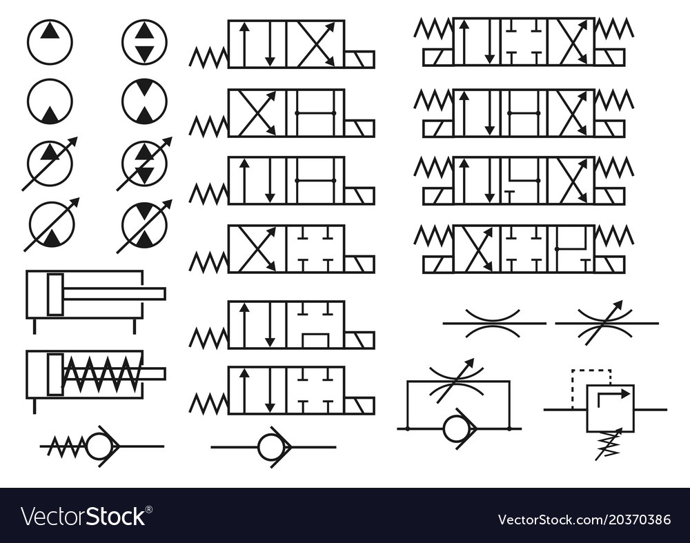
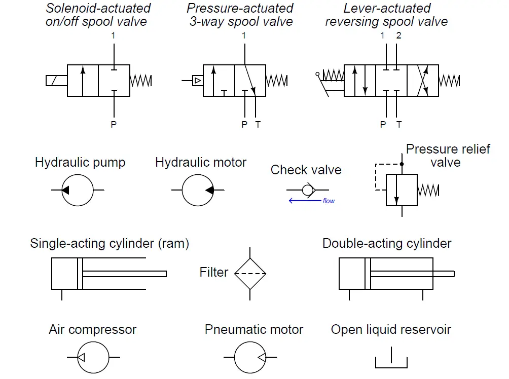
The lower end (suction side) of a pump is connected to the hydraulic reservoir, the upper end is connected to the remaining circuit. The dark upper triangle in these hydraulic symbols indicates fluid going out of the system and hence represents a pump. In the case of the hydraulic motor, the dark triangle is inverted indicating that the fluid.

A guide to common hydraulic symbols EngineeringClicks Hydraulic, Hydraulic systems
A pressure relief valve is a normally closed valve that senses the high pressure at its inlet. As the pressure at the inlet increases, the pressure in the pilot line begins to push against the valve body (spool). As the valve body moves, the ports begin to line up and fluid will begin flow-ing through the relief valve.
Hydraulic Valve Symbols Autocad energyfabric
See Full PDFDownload PDF. Hydraulic symbols Energy conversion Energy transfer Actuation Valves Valves Valves line, supply line, return line, component framing Manual actuation Basic symbols Directional control valves Stop valves and symbol boxed in A A B internal and external pilot line, leakage oil line, shut-off valve 3-way stop-cock.

Basic Knowledge of hydraulic and hydraulic Symbols YouTube
Directional Control Valves. Variable Displacement. 2-way, normally closed (NC) 2-way, normally open (NO) 3 way, 2 position. 4-way, 2 position 4 way, 3 position.

Hydraulic Symbols.pdf
SHUT-OFF VALVE. ACCUMULATOR WITH. GAS PRE-CHARGE Tel. +34 93 812 46 64. Pedro Roquet, s/a Antonio Figueras, 91 08551 TONA (Barcelona) SPAIN Fax +34 93 887 17 98. Web: www.pedro-roquet.com. Hydraulic Symbols.pdf - Free download as PDF File (.pdf), Text File (.txt) or view presentation slides online.
Hydraulik Schaltzeichen und Symbole auf einen Blick verstehen
Working hydraulic line Pilot line Drain line Direction of flow Hose or other flexible working line Lines crossing (no connection) Lines connecting Fixed) throttle, lines with
Set of hydraulic symbols Royalty Free Vector Image
Pneumatic energy source (gas energy) Hydraulic energy source (liquid energy) Permanent magnet Port exhausting to atmosphere Exhaust4 to atmosphere Three-way rotary connection
Diagrammer JO Hydraulics A/S
wwwabdecom 591 general engineering - hydraulic symbols direct operated ("single-stage") relief valve with adjustable spring Pilot operated ("two-stage") relief valve

Iso hydraulic symbols chart pdf United States manuals Cognitive Instructions
Fluid power symbols can be thought of as the letters in the language of fluid power. As such, they are universal; they are not dependent on a knowledge of the designer's spoken language, but are understood by anyone familiar with the symbols. The chart below shows many of the symbols (letters) in the language of fluid power.
Hydraulische symbolen MVWautotechniek.nl
Diamond. -continuous line - flow line. -dashed line - pilot, drain. -envelope - long and short dashes around two or more component symbols. -large circle - pump, motor. -small circle - Measuring devices. -semi-circle - rotary actuator. -one square. - pressure control function.

What’s the Difference Between Hydraulic Circuit Symbols? Machine Design Hydraulic, Piping
Created Date: 4/9/2002 4:20:36 PM
Fluid Power Systems Hydraulic System Working Instrumentation Tools
XIII Fluid Power Graphic Symbols AIR LINE PRESSURE REGULATOR adjustable, relieving LUBRICATOR with automatic filling LUBRICATOR with manual drain LUBRICATOR

hydraulic circuit symbols
Fluid Power Symbols 3.9.5 With One Check 3.11 Rotating Coupling 4. Energy Storage and Fluid Storage 4.1 Reservoir Note: Reservoirs are conventionally drawn in the