Motorcycle Master Diagram
Here's how a brake booster and master cylinder work to stop your vehicle with the press of your brake pedal.Stopping a heavy, 2000+ lb car is no easy task. I.
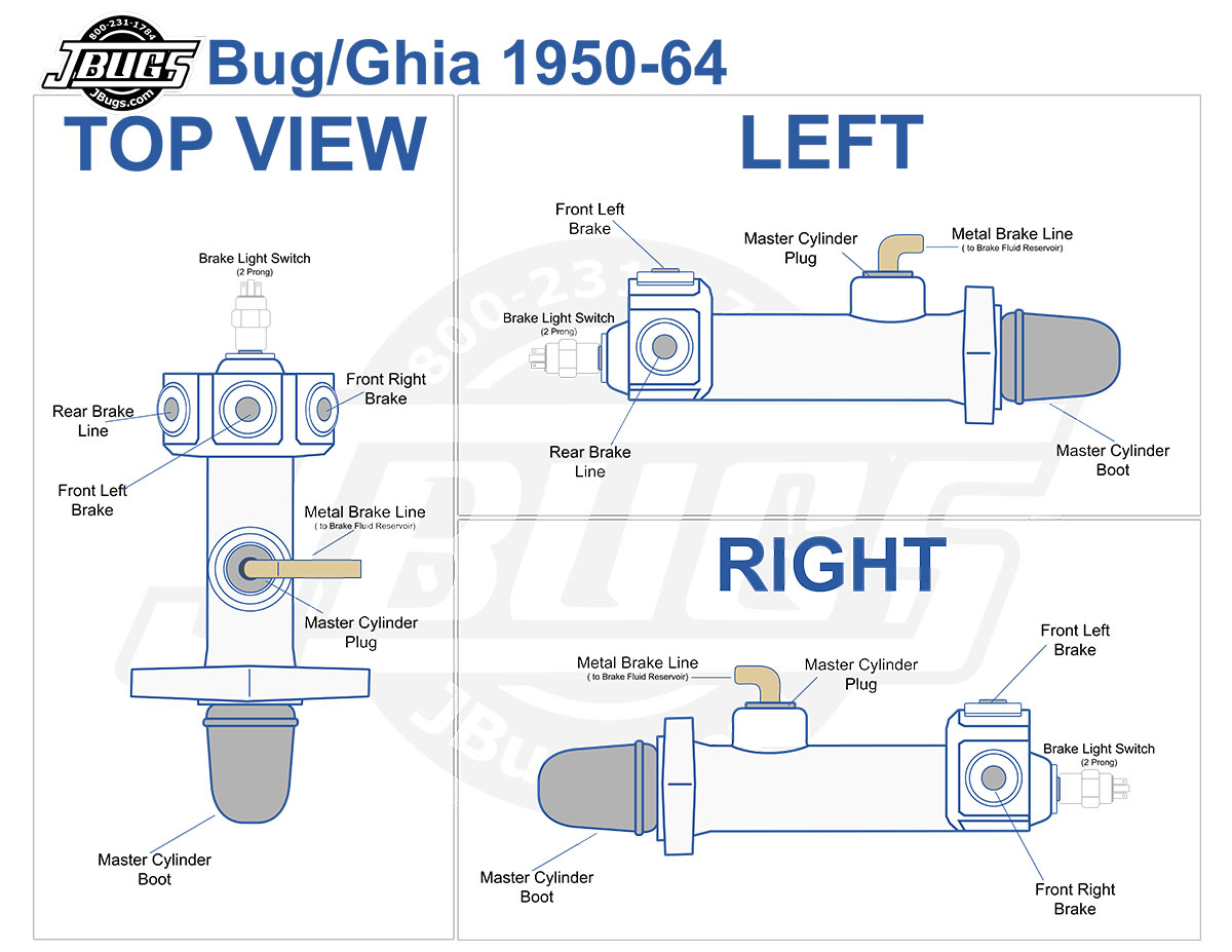
VW Parts Master Cylinder Installation Diagrams
Its Diagram, Parts, Function, Types, and Symptoms are explained in detail. Also, you can download the free PDF file of this article at the end. What is a Master Cylinder? Contents show The master cylinder is a device that converts force (usually from the driver's foot) into hydraulic pressure.

Master Cylinder Diagram Diagram, Science diagrams, Cylinder
By definition, a Master cylinder is a cylinder or water-powered gadget that uses pistons and cylinders that are arranged in such a way that the mechanical power exerted on the brake pedal by the driver of the vehicle or the brake switch in bicycles is converted to a water-driven load. The load is thus used for braking by the brake caliper.
:max_bytes(150000):strip_icc()/1280px-Master_cylinder_diagram.svg-5a172d594e46ba001a8294ac.png)
Symptoms of Master Cylinder Failure
A disc/drum master cylinder requires more fluid vol-ume for the disc brake circuit, so the disc reservoir will be larger. An original disc/drum master cylinder may feature a built-in residual valve for the drum brake circuit. If a replacement disc/drum master cylinder is selected, an ex-ternal residual valve may need to be added. 18 October 2012
What Is Master Cylinder? Types of Master Cylinders Working
The master cylinder is a crucial hydraulic component within the braking system of automobiles, employing a cylinder and one or two pistons arranged in a manner that transforms the mechanical force exerted by the vehicle's driver, either through the brake pedal (in cars) or brake lever (in bikes), into hydraulic pressure.
Master Cylinder and Related Diagram View Chicago Corvette Supply
This video is primarily directed towards my first-year students attending Brakes class where we take an in-depth look at a quick take-up master cylinder desi.

Repair Guides Clutch Master Cylinder
In automotive engineering, the master cylinder is a control device that converts force (commonly from a driver's foot) into hydraulic pressure. [1] This device controls slave cylinders located at the other end of the hydraulic brake system.
Master Cylinder Slave Cylinder Diagram General Transmission
What is a Master Cylinder Line Diagram? A master cylinder line diagram is a schematic representation of the hydraulic brake system in a vehicle. It provides a visual reference of how the brake lines and components are connected and arranged in the system.
Master Cylinder Diagram My Wiring DIagram
Subscribe Subscribed 541K views 5 years ago Master cylinders are an important component of many vehicles. They convert the applied force of the foot or fingers into hydraulic pressure. A master.

Repair Guides Hydraulic Brake Systems Master Cylinder
The brake master cylinder can be found at the back of this diagram, with… Each piston corresponds to a different brake 'circuit' which doubles up as an added safety measure. One piston is.

Chevy Master Cylinder Parts
Diagram of master cylinder The Master Cylinder in Action When you press the brake pedal, it pushes on the primary piston through a linkage. Pressure builds in the cylinder and lines as the brake pedal is depressed further. The pressure between the primary and secondary piston forces the secondary piston to compress the fluid in its circuit.
Master Cylinder Assembly Diagram View Chicago Corvette Supply
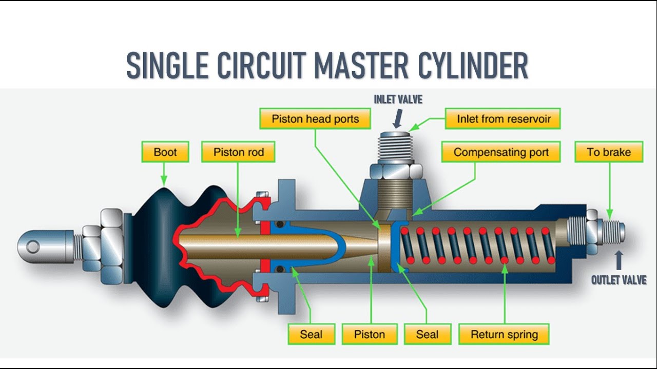
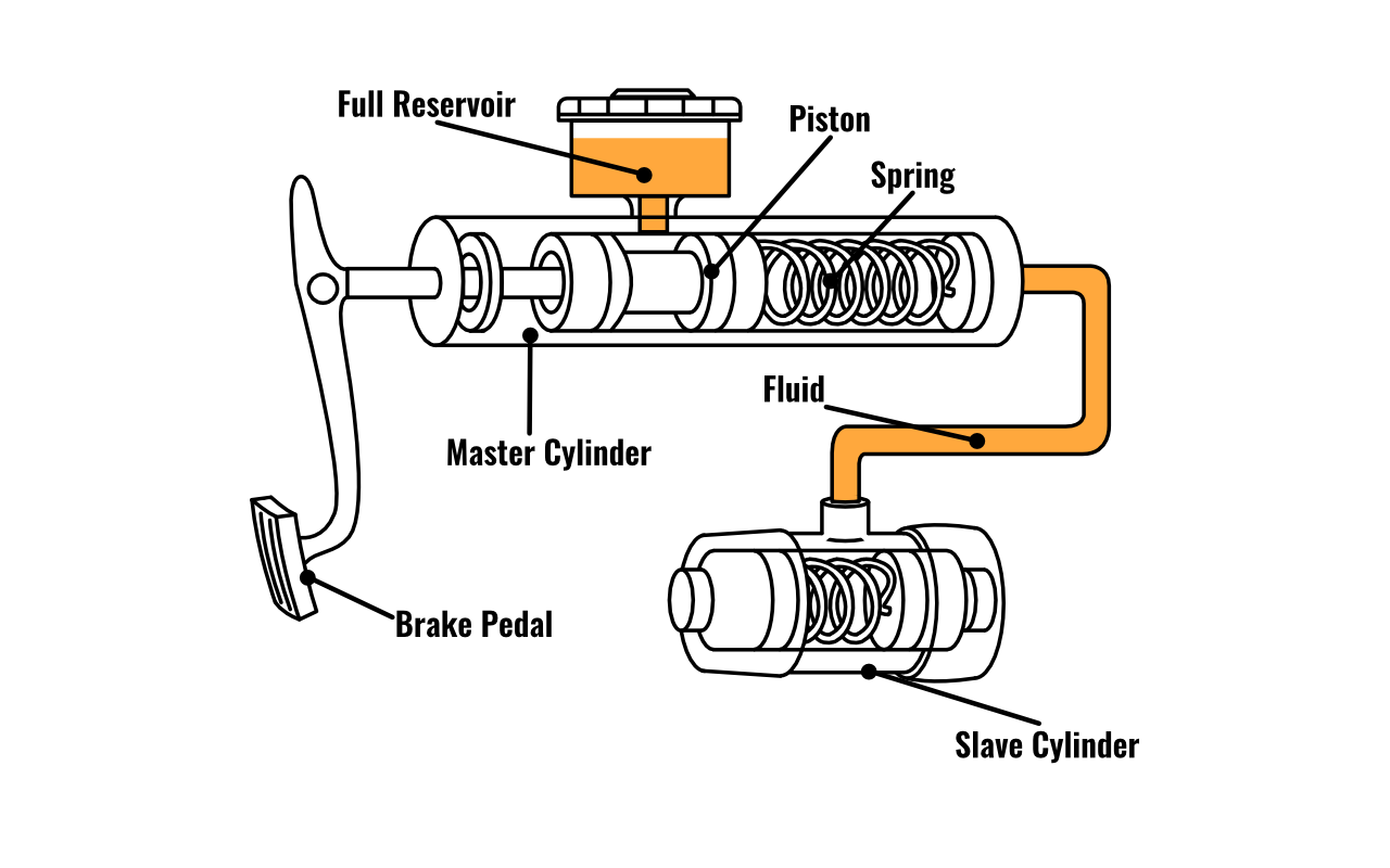
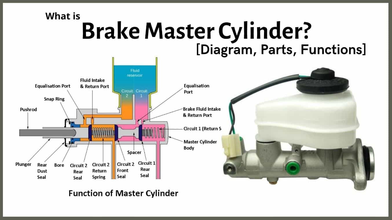
Master cylinder diagram The master cylinder is an assembly of many parts. The main working parts of the master cylinder are shown in the diagram below- The notable parts shown in the above diagram are- Reservoir, cylinder, piston, valve, spring and braking pedal. We shall study in detail about them in below sections. Master cylinder parts
shivy Master cylinder
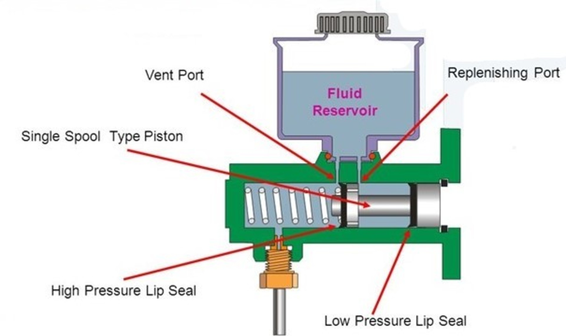
Diagram Of Master Cylinder : The principle of working is that of Pascal's Law where a high pressure fluid is obtained at the outlet of smaller area, of a cylinder by application of force on the larger area inlet area. hydraulic master cylinders The below picture is a cut section of a BMC.
Master Cylinder Diagram, Parts, Function, Symptoms [PDF]
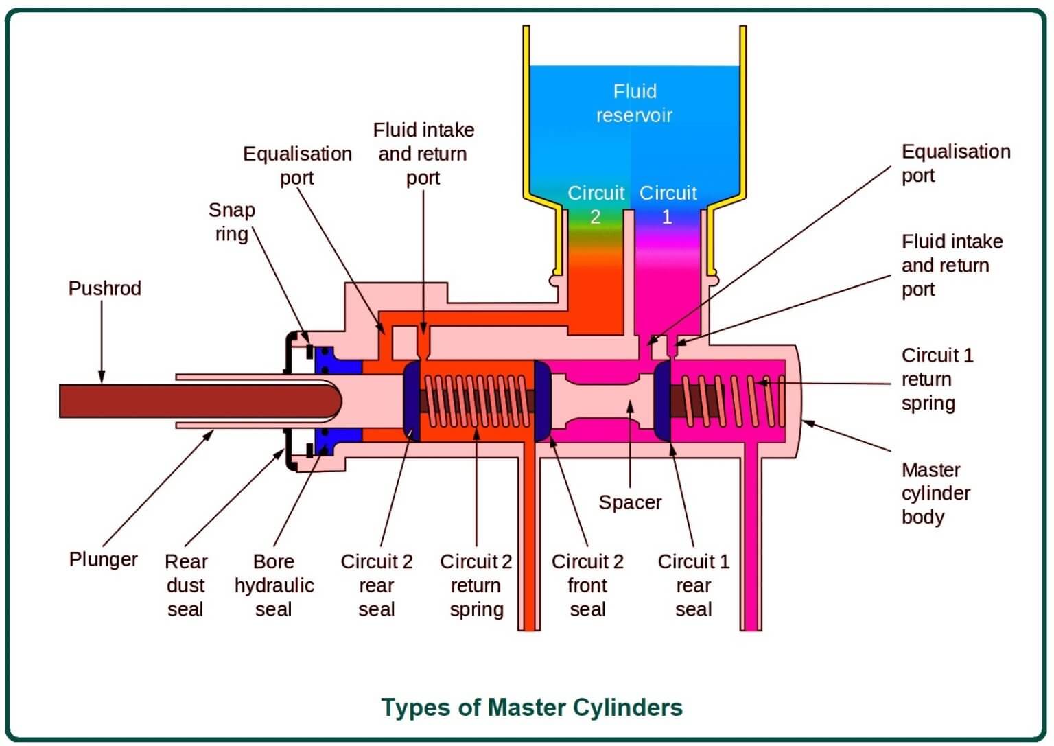
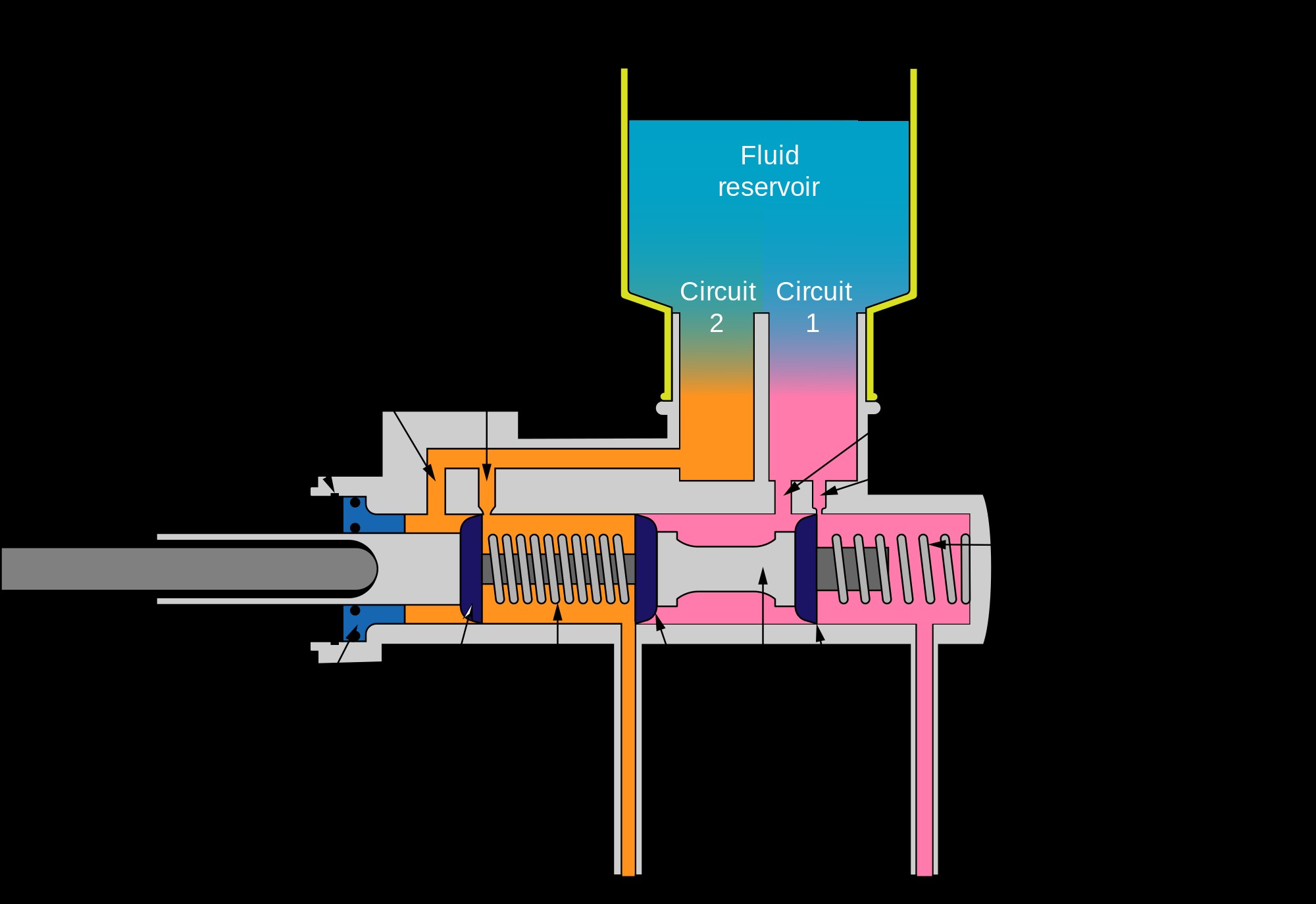
How it Works In essence, a master cylinder is a pump, and operation of the dual master cylinder is simple. When the brake pedal is depressed, force is applied through the push-rod to the master cylinder piston. The piston actually has two seals, and pushes in two chambers of the master cylinder, with a line to each circuit.
Classic Car Brake Master Cylinder Types Classic Auto Advisors
Dual master cylinders have two separate chambers that separate the front and rear brake circuits. This type of system prevents the total loss of braking action in the event of brake fluid loss. The brake circuits can be split front and back or diagonally.

Repair Guides Hydraulic System Master Cylinder
Diagram of master cylinder When the brake pedal is depressed, it pushes on the first (primary piston) through a linkage. The Pressure builds in the cylinder and lines as the brake pedal is depressed further. The pressure between the primary and secondary piston forces the secondary piston to compress the fluid in its circuit.