
How To Make A Logic Truth Table
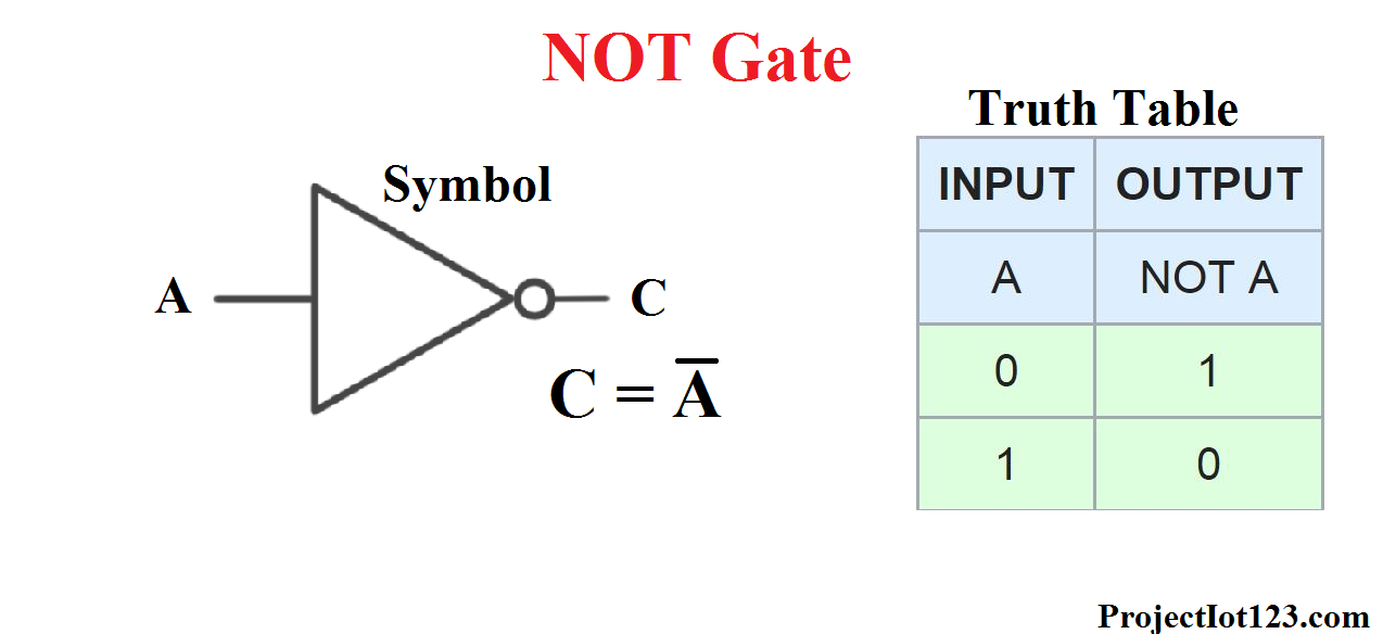
The Truth Table of NOT Gate. The truth table of NOT gate is as shown below When the input is high/logic 1/true the respective output is low/logic 0/false and vice versa. The waveform of a NOT gate is as follows: If you are reading NOT Gate, then you should also read about OR Gate.

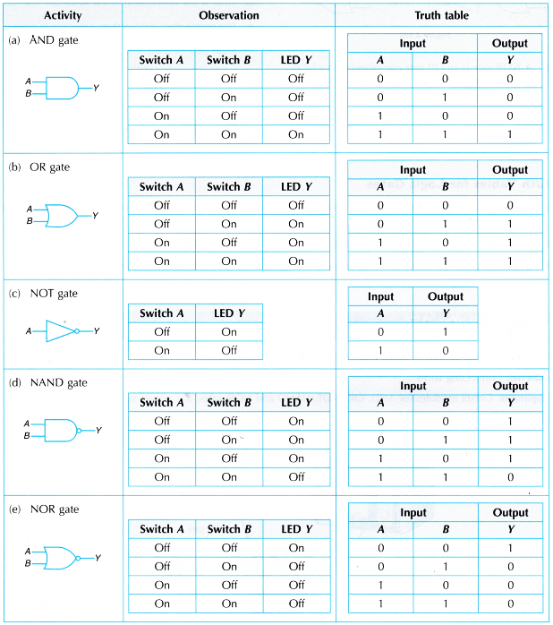
The truth tables of logic gates A, B, C, D are given here. Identify them correctly.
NOT GATE We will build a device with one input and one output. We will give the device an input, either True (1) or False (0). The device will give us an output (either True or False) to tell us what happened as a result of our input. Later we will build devices with more inputs and outputs so it can do more complex things for us.

Logic Gates Truth Table Logic Gates Truth Tables Boolean Expressions Photos Apart from
A table that lists all the combinations of input variables and the corresponding outputs is called a truth table. It shows how the logic circuit's output responds to various combinations of logic levels at the inputs. What is NOT Gate?

truth table to circuit Wiring Diagram
Not gate is one of the basic logic gate. NOT operator works on a single input and it performs the complement operation. If you enter 0 as input it will perform complementation operation on it and produce output as 1 and vice-versa. Please check our video tutorial on what is not gate?

Truth Table For Xor Gate
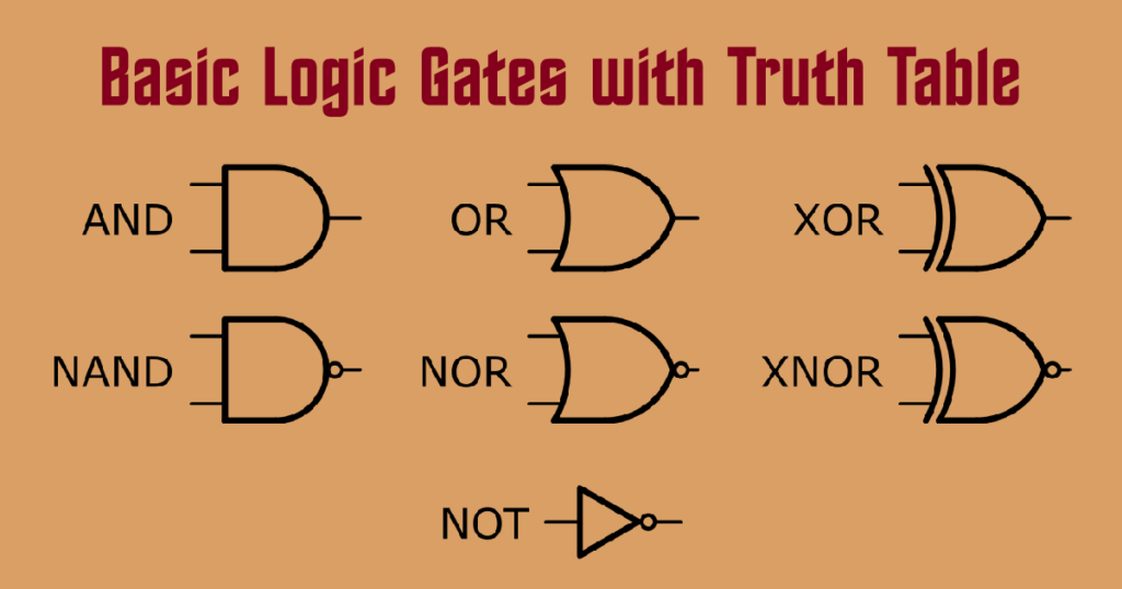
The truth table of a NOT gate can be represented as: Other logic gates include AND gates, OR gates, NAND gates, NOR gates, XOR gates, XNOR gates. NOT Gate Transistor Circuit Diagram A NOT gate can easily be realized by using a simple bipolar transistor.
Ideas In And Truth Table Photos Darkata
The NOT gate is a single input single output gate. This gate is also known as Inverter because it performs the inversion of the applied binary signal, i.e., it converts 0 into 1 or 1 into 0. In other words, the gate which has a high input signal only when their input signal is low such type of gate is known as the not gate. The logic symbol for.

Logic Gates AND, OR, NOT, NOR, NAND, XOR, XNOR Gates Truth Table YouTube
This electronics video provides a basic introduction into logic gates, truth tables, and simplifying boolean algebra expressions. It discusses logic gates s.
Logic Gates Truth Table And Diagram Elcho Table
The truth table reiterates the function of a NOT gate, which is worth stating formally. Rule: NOT Gates A NOT gate is a logic gate with one binary input and one binary output. The function of a NOT gate is to invert a value so that the input value is not the output.
Logic Gates and Truth tables Inst Tools
Truth Table: The outputs for all conceivable combinations of inputs that may be applied to a logic gate or circuit are listed in a truth table. When we enter values into a truth table, we usually express them as 1 or 0, with 1 denoting True logic and 0 denoting False logic. Types of Logic Gates

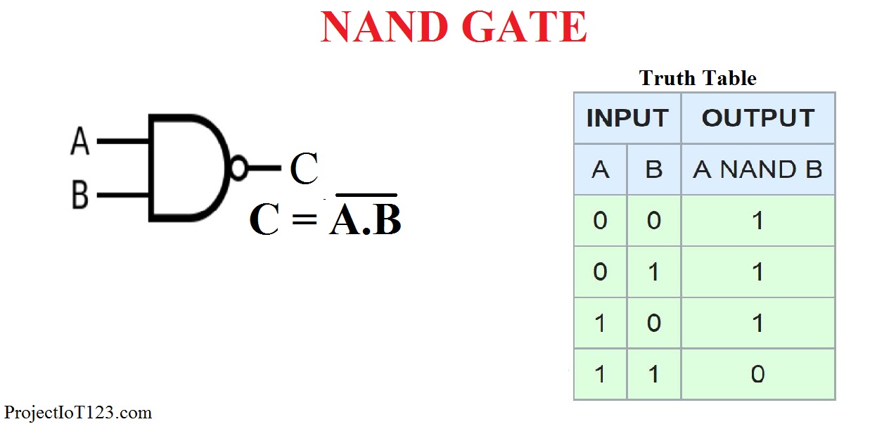
Introduction to NOR Gate projectiot123 is making esp32,raspberry pi,iot projects
Fig. 1 The operation of NOT gate is based on the following rule: The output of a NOT gate is logical 1 (high) if input is logical 0 (low). The output of a NOT gate is logical 0 (low) if input is logical 1 (high). NOT gate Truth table Switch Circuit of NOT gate Fig. 2 The switch circuit having function similar to the NOT gate is shown in figure 2.
Introduction to logic gates projectiot123 is making esp32,raspberry pi,iot projects
The truth table of a NOT gate summarizes its behavior for all possible input combinations. The following table shows the 2-input NOT Gate truth table: How does a NOT Gate work? The NOT gate accomplishes this by using a transistor to switch between two states, allowing it to invert the input signal.

Pin on Electronic
What is a NOT Gate? Logic Symbol and Truth Table. The NOT gate is also known as the inverter gate. It inverts the input logic. If the input of the NOT gate is 1, then the output is 0, and vice versa. In digital electronics, the NOT gate is a basic logic gate consisting of a single input and a single output. The NOT or inverter gate gives a HIGH.
Introduction to logic gates projectiot123 Technology Information Website worldwide
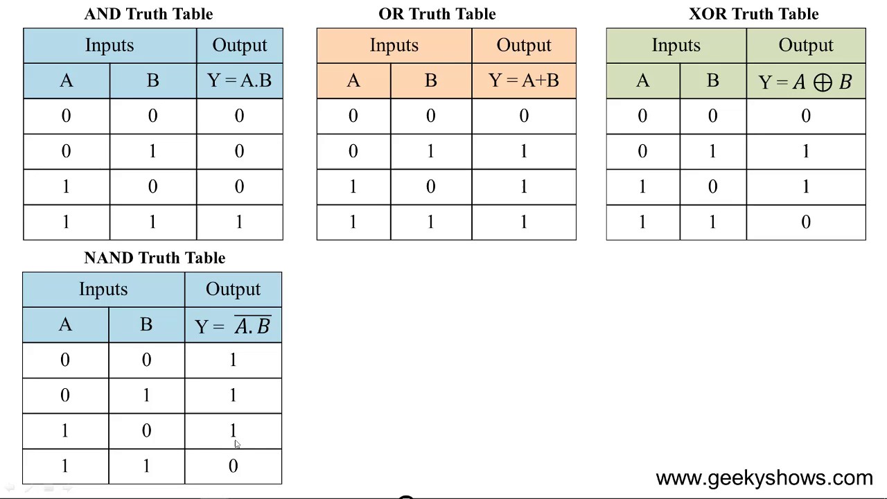
As well as a standard Boolean Expression, the input and output information of any Logic Gate or circuit can be plotted into standard Boolean Algebra truth tables to give a visual representation of the switching function of the system.. The table used to represent the boolean expression of a logic gate function is commonly called a Truth Table.A logic gate truth table shows each possible input.
Basics of Logic Gates with Truth Table AHIRLABS
The truth table is used to show the logic gate function. All the logic gates have two inputs except the NOT gate, which has only one input. When drawing a truth table, the binary values 0 and 1 are used. Every possible combination depends on the number of inputs.
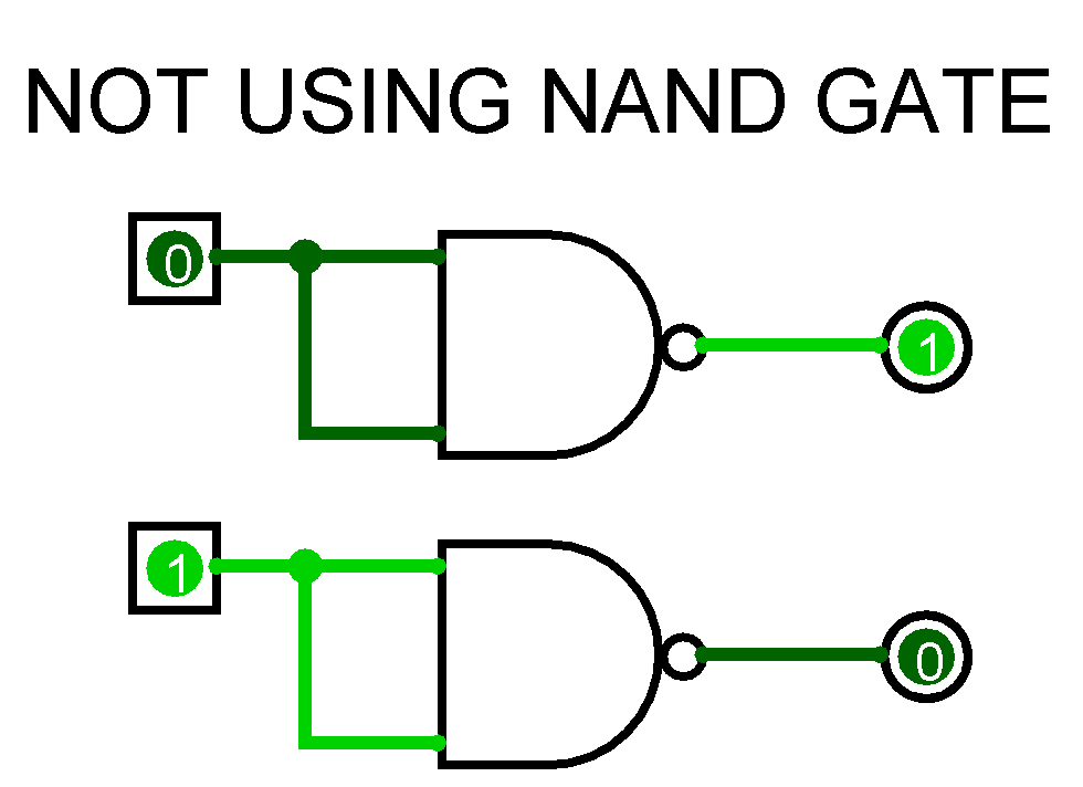
Circuit Diagram Of Not Gate Using Nand Wiring View and Schematics Diagram
The Logic NOT Gate Truth Table Logic NOT gates provide the complement of their input signal and are so called because when their input signal is "HIGH" their output state will NOT be "HIGH". Likewise, when their input signal is "LOW" their output state will NOT be "LOW".

NOR Gate Logic Gates Tutorial
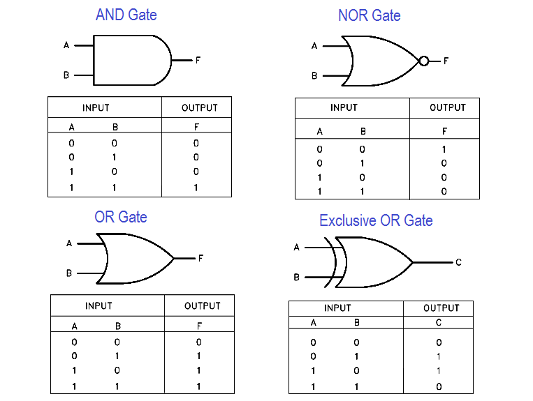
Access Rights using Binary Masks. Learning Objectives In this post you will predict the output of logic gates circuits by completing truth tables. First you need to learn the basic truth tables for the following logic gates: AND Gate OR Gate XOR Gate NOT Gate First you will need to learn the shapes/symbols used to draw the four main logic.