
Ford Ignition Switch Wiring Diagram Wiring Harness Diagram
A basic guide on how to connect an ignition switch to cars and other vehicles. We will examine what wires that go to the switch and how to connect them. By Magnus Sellén Updated: January 7, 2023 If you are looking at replacing or repairing an ignition switch, it helps to know more about the wiring.
43 5 prong ignition switch wiring diagram
A wiring diagram for an ignition switch can help you understand how the system works. The diagram will show the various components and how they are connected. The contacts points will be labeled, as well as the power source and the power output. It is important to note that the diagram will indicate whether the power source is positive or negative.

[Download 23+] Universal Ignition Switch Wiring Diagram
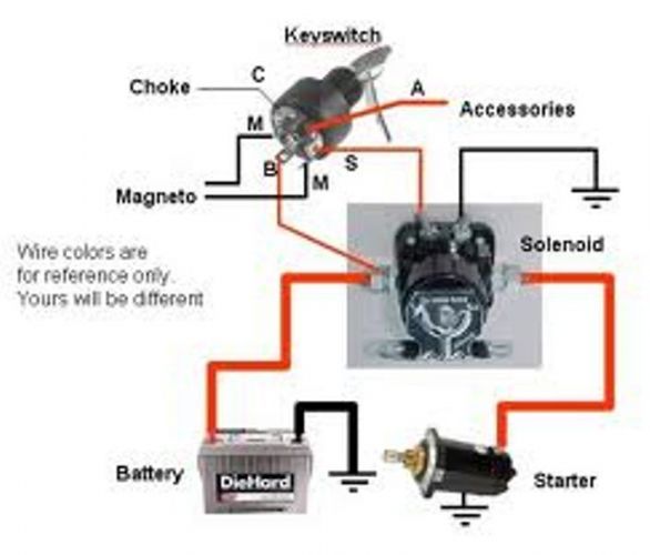
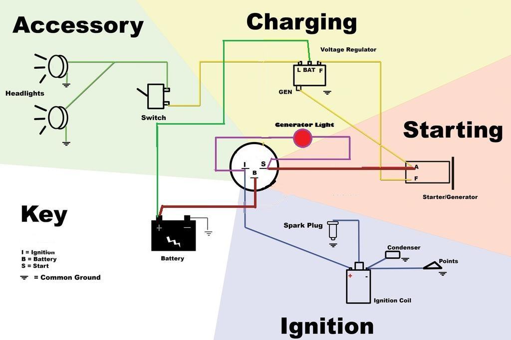
Step 1: Obtain a circuit diagram Step 2: Locate all components that need wiring Step 3: Connect the switch to ground Step 4: Connect the switch to the Solenoid Step 5: Wire the magneto to the switch Step 6: Provide voltage by connecting the battery Step 7: Connect the accessories/ lights Step 8: Screw the switch in place
5 Terminal Ignition Switch Wiring Diagram
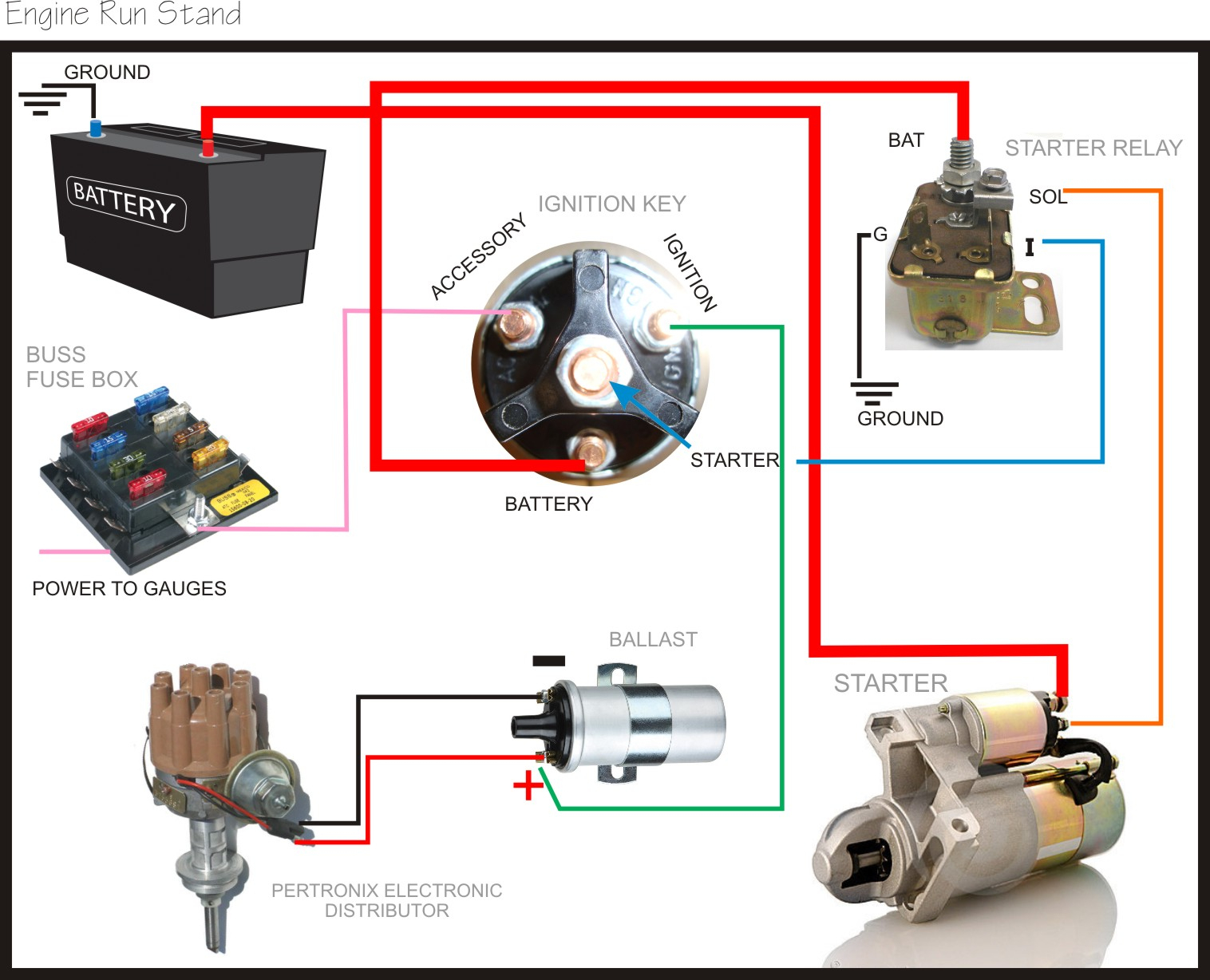
1. Park Your Vehicle: Make sure your car is parked on flat ground before turning off the engine. 2. Locate the Terminals on the Ignition Switch: Look for the pins at the back of the ignition switch. You would find four terminals with marks like "BATT" (Battery), "ST" (Start), "IGN" (Ignition), and "ACC" (Accessory).
Simple Ignition Wiring Diagram
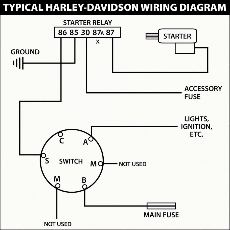
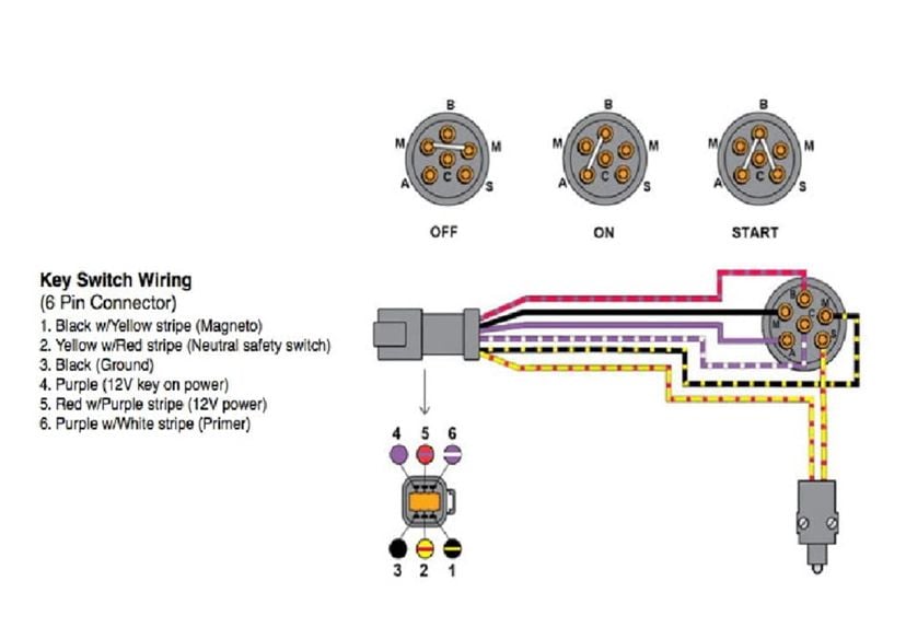
To ignition system To starter motor solenoid To accessories e.g. radio, lights, cigar sockets etc. IGNITION SWITCH Brass terminals on switch Wiring Diagram For 4 Position Universal Ignition Switch Product Code P00940
23+ 5 Pole Ignition Switch Wiring Diagram Pictures
As the name implies, the ignition switch is in charge of triggering the circuits or signals that start the vehicle. You must know how to use your ignition switch, especially when the central electrical system goes bad. It's also good that you know to do this in an emergency.
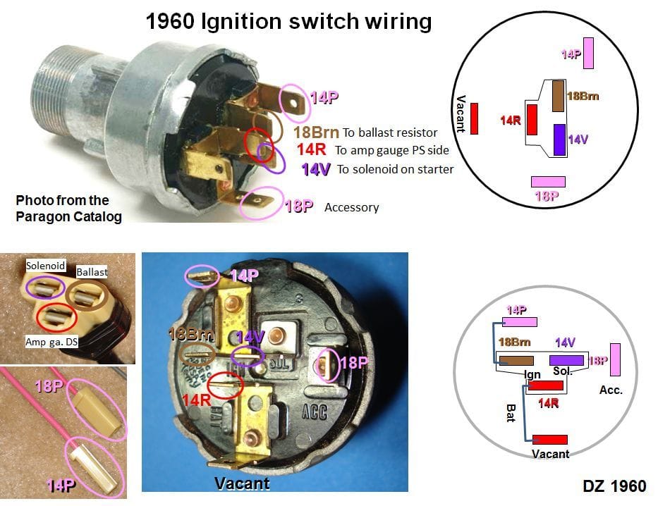
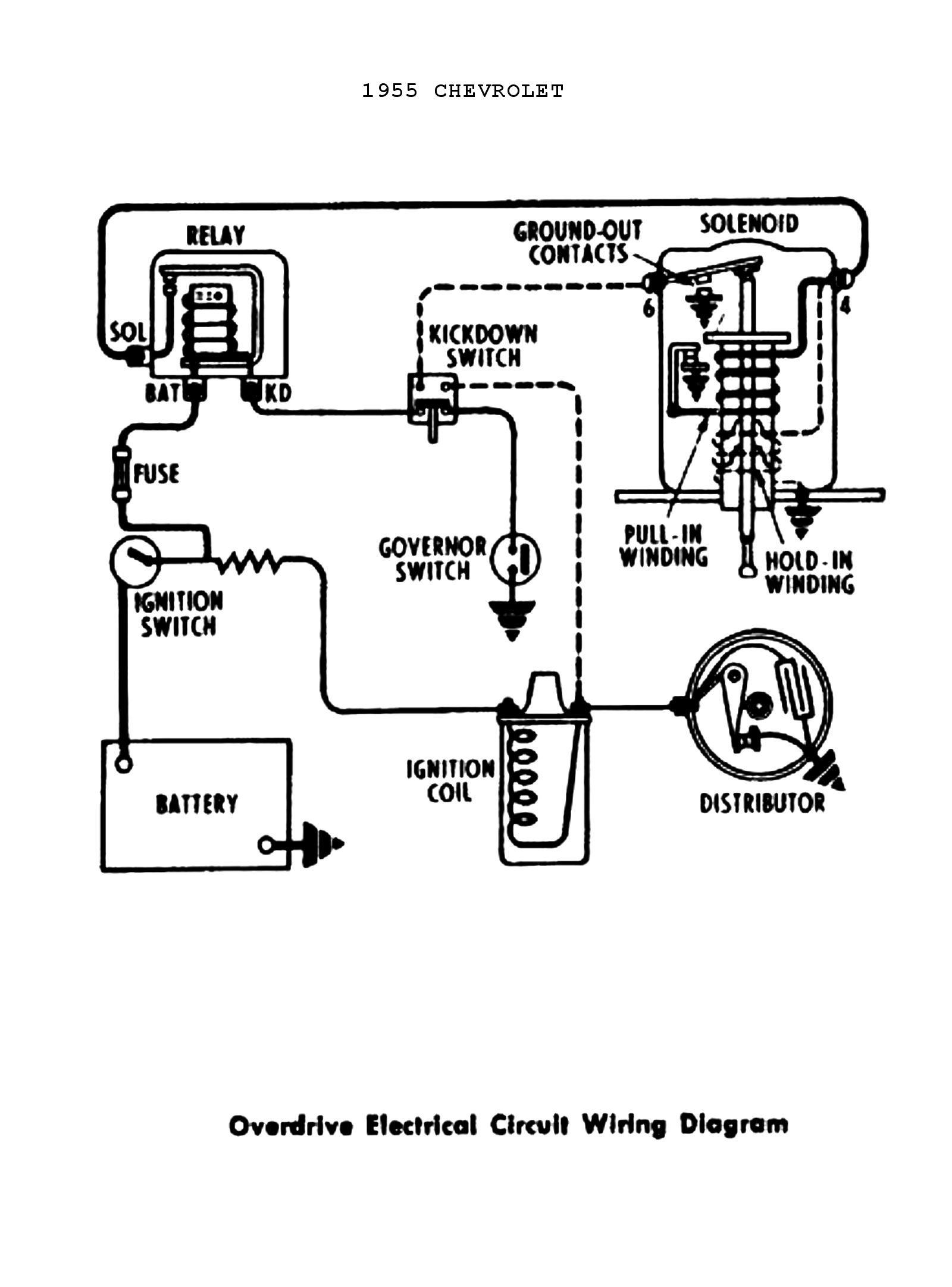
Technical Ignition switch wiring diagram 1955.2 Chevy 3100 The H.A.M.B.
What wires go to the ignition switch? If you own a modern car, it most likely has a 4-wire ignition switch. These switches typically have four terminals with the labels: BATT (battery). A thick red wire that is always energized usually connects here. IGN (ignition input).

Wiring Diagram Ignition Switch
4 Wire Ignition Switch Diagram: There are four wires that run from the ignition switch to the engine. These are the white wire, the black wire, the red wire, and the green wire. The white wire is always hot, and it goes to the distributor. The black wire is always ground, and it goes to the battery.
Simple Ignition Switch Wiring Diagram
HOW TO WIRE TRACTOR IGNITION KEY STARTER SWITCH aka UNIVERSAL IGNITION SWITCH. Best Explained! Everything you need to know how to wire tractor universal ign.

Leah Schema 1955 Chevy Bel Air Ignition Switch Wiring Diagram 1957 Chevy Bel Air Ignition
A wiring diagram for an ignition switch diagram can help you identify which wires go where, and how they should be connected. This type of diagram is especially useful when installing a new system or troubleshooting an existing one. Understanding The Electrical Circuit

Indak Ignition Switch Wiring Diagram
This wiring diagram shows how to connect your MASTERCELL inputs to a typical ignition switch. Image of wiring diagram showing how to wire an ignition switch with the Infinitybox system. As mentioned above, the MASTERCELL inputs work by getting connected to ground. To do this, you are going essentially wire the switch backwards.
Typical Ignition Switch Wiring Diagram Wiring Diagrams Hubs Boat Ignition Switch Wiring
**PARTS LIST IN DESCRIPTION BELOW**Adding a push button start ignition to a race car is pretty darn cool, and these days you can easily buy all the parts you.

Ignition Switch Wire Diagram Wiring Draw
Most cars have four wires connected to the back of the ignition switch, labeled BATT, IGN, ST, and ACC. The BATT wire is a thick red wire that is always energized. The IGN terminal controls your vehicle's ignition and other electronics and is usually connected with a yellow or red wire.

5 Terminal Ignition Switch Wiring Diagram
ACC (Accessory). The ACC terminal transmits power to the car accessories like the radio, the lights, the windshield wiper, and many others. The ACC usually has a purple-coated wire. You must understand which wire goes to where in the ignition switch if you are planning to troubleshoot or replace it.
3497644 Ignition Switch Diagram Dealers Mangonui Mowers Chainsaws Ltd / This applies to all
Part 1 Accessing the Ignition Download Article 1 Disconnect the negative terminal on the battery. Turn the car off if you can, pop the hood, and locate your battery. The battery is the black box with a positive (+) and negative (-) post sticking out of the top of it.
7 Terminal Ignition Switch Wiring Diagram Diagram Niche Ideas
5 Pole Ignition Switch Wiring Diagram: Step 1 Park the vehicle and start by opening your hood, check the negative terminal of the battery, and detach the terminal locking nuts holding it to the negative post on the battery.